Lighting device that suppresses excessive temperature rise of light emission section, method of controlling same, and image capture apparatus

a technology of light emission section and light source, which is applied in the direction of lighting and heating equipment, instruments, television systems, etc., can solve the problems of excessive rise of temperature of the components damage to the members etc., and achieve the effect of suppressing an excessive temperature rise of the light emission section

Active Publication Date: 2022-11-15
CANON KK
View PDF21 Cites 0 Cited by
  • Summary
  • Abstract
  • Description
  • Claims
  • Application Information

AI Technical Summary

Benefits of technology

[0005]The present invention provides a lighting device capable of suppressing an excessive temperature rise of a light emission section even when a fan becomes incapable of normal rotation, a method of controlling the same, and an image capture apparatus including the lighting device.
[0009]According to the present invention, it is possible to suppress an excessive temperature rise of the light emission section even when the fan is incapable of normal rotation.

Problems solved by technology

The temperature of the inside of the light emission section is increased by continuous light emission operation, and hence there is a fear that members as components of the light emission section suffer damage, such as deformation, due to the temperature rise of the light emission section.
However, in the lighting device disclosed in Japanese Patent No. 5246310, even when such a problem that the fan does not normally rotate has occurred due to expiration of service life or failure of the fan, light emission from the light emission section is performed as usual, and hence there is a fear that the temperature of the components of the light emission section excessively rises since the light emission section is not cooled.

Method used


Image

  • Lighting device that suppresses excessive temperature rise of light emission section, method of controlling same, and image capture apparatus
  • Lighting device that suppresses excessive temperature rise of light emission section, method of controlling same, and image capture apparatus
  • Lighting device that suppresses excessive temperature rise of light emission section, method of controlling same, and image capture apparatus

Examples


Embodiment Construction

[0023]The present invention will now be described in detail below with reference to the accompanying drawings showing embodiments thereof.

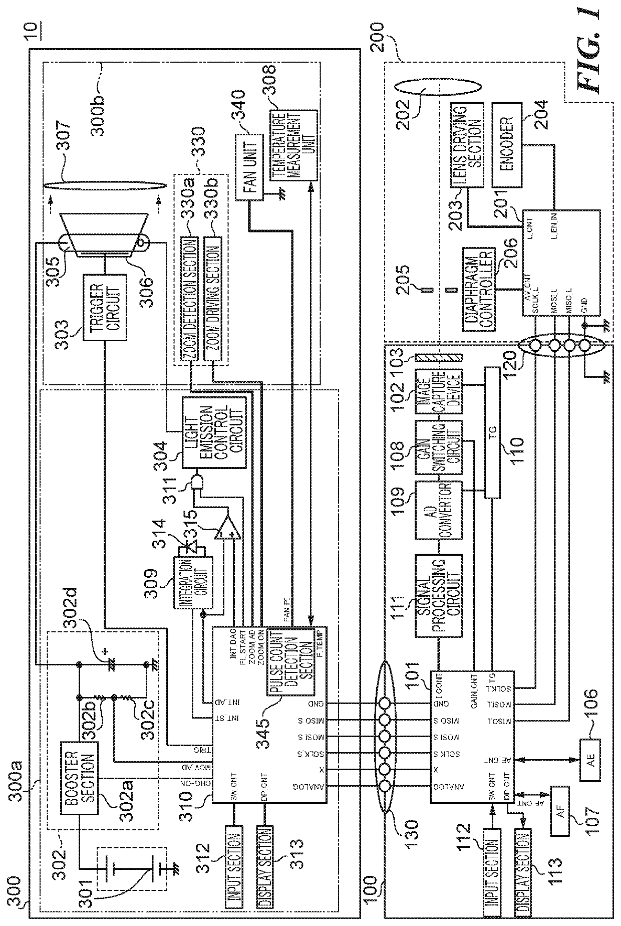
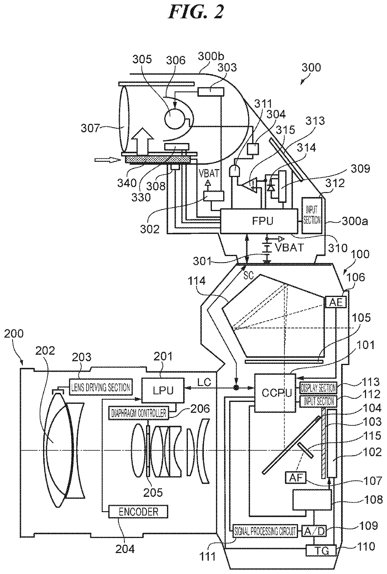
[0024]FIG. 1 is a schematic block diagram of an image capture system including a lighting device according to a first embodiment of the present invention. FIG. 2 is a schematic cross-sectional view of the image capture system, denoted by reference numeral 10. Note that the same component elements in FIGS. 1 and 2 are denoted by the same reference numerals. Further, some of the component elements appear in FIG. 1, but not in FIG. 2, and others of the component elements appear in FIG. 2, but not in FIG. 1.

[0025]The image capture system 10 includes a camera body 100 which is an image capture section having an image capture function, a lens unit 200 attached to the camera body 100, and a lighting device 300 which is a strobe device attached to the camera body 100. The lighting device 300 is removably mounted on the camera body 100, The lens unit 200 m...


PUM

PropertyMeasurementUnit
voltageaaaaaaaaaa
timeaaaaaaaaaa
time periodaaaaaaaaaa

Abstract

A lighting device capable of suppressing an excessive temperature rise of a light emission section even when a fan is incapable of normal rotation. The light emission section emits light for illuminating an object. The fan cools the light emission section. A motor driving section drives the fan for rotation. A strobe microcomputer determines whether or not the motor driving section is abnormal, and controls a light emission interval of the light emission section in continuous light emission, based a result of the determination.

Description

BACKGROUND OF THE INVENTIONField of the Invention[0001]The present invention relates to a lighting device including a light emission section that emits light for illuminating an object and a fan for cooling the light emission section, and a method of controlling the same, and an image capture apparatus.Description of the Related Art[0002]A lighting device, such as a strobe device, used in an image capture apparatus has a light emission section including a xenon tube, a reflection umbrella, and a Fresnel panel. The temperature of the inside of the light emission section is increased by continuous light emission operation, and hence there is a fear that members as components of the light emission section suffer damage, such as deformation, due to the temperature rise of the light emission section. To avoid this damage, there has been proposed a lighting device provided with a fan for cooling the light emission section.[0003]For example, Japanese Patent No. 5246310 discloses a lighting...

Claims


Application Information

Patent Timeline
Patent Type & Authority Patents(United States)
IPC IPC(8): H04N5/225G03B15/05H05K7/20
CPCG03B15/05H04N5/2256H05K7/20172H05K7/20209G03B2215/0503F21V29/67H04N23/56G03B2215/0514Y02B20/40
Inventor ICHIHARA, YOSHIRO
Owner CANON KK
Why Eureka
Try Eureka