Fuel cell system control method and fuel cell system

a fuel cell and system control technology, applied in the direction of fuel cells, reactant parameter control, electrical equipment, etc., can solve the problems of excessive oxygen condition and deterioration of the reforming performance of the fuel processor, and achieve the effect of suppressing excessive temperature ris

Active Publication Date: 2020-05-28
NISSAN MOTOR CO LTD
View PDF1 Cites 0 Cited by
  • Summary
  • Abstract
  • Description
  • Claims
  • Application Information

AI Technical Summary

Benefits of technology

[0005]The object of the present invention is to provide a fuel cell system control method and a fuel cell system, which suppress excessive temperature rise at the starting-up.

Problems solved by technology

When supplying a cathode gas before supplying a fuel gas, oxygen is in an excessive condition compared to the fuel gas at the timing at which the fuel gas is supplied.
For that reason, a reaction between the fuel gas and oxygen becomes easy to progress and the fuel processor has temperature excessively raised locally and thus the reforming performance of the fuel processor may be deteriorated.

Method used


Image

  • Fuel cell system control method and fuel cell system
  • Fuel cell system control method and fuel cell system
  • Fuel cell system control method and fuel cell system

Examples


first embodiment

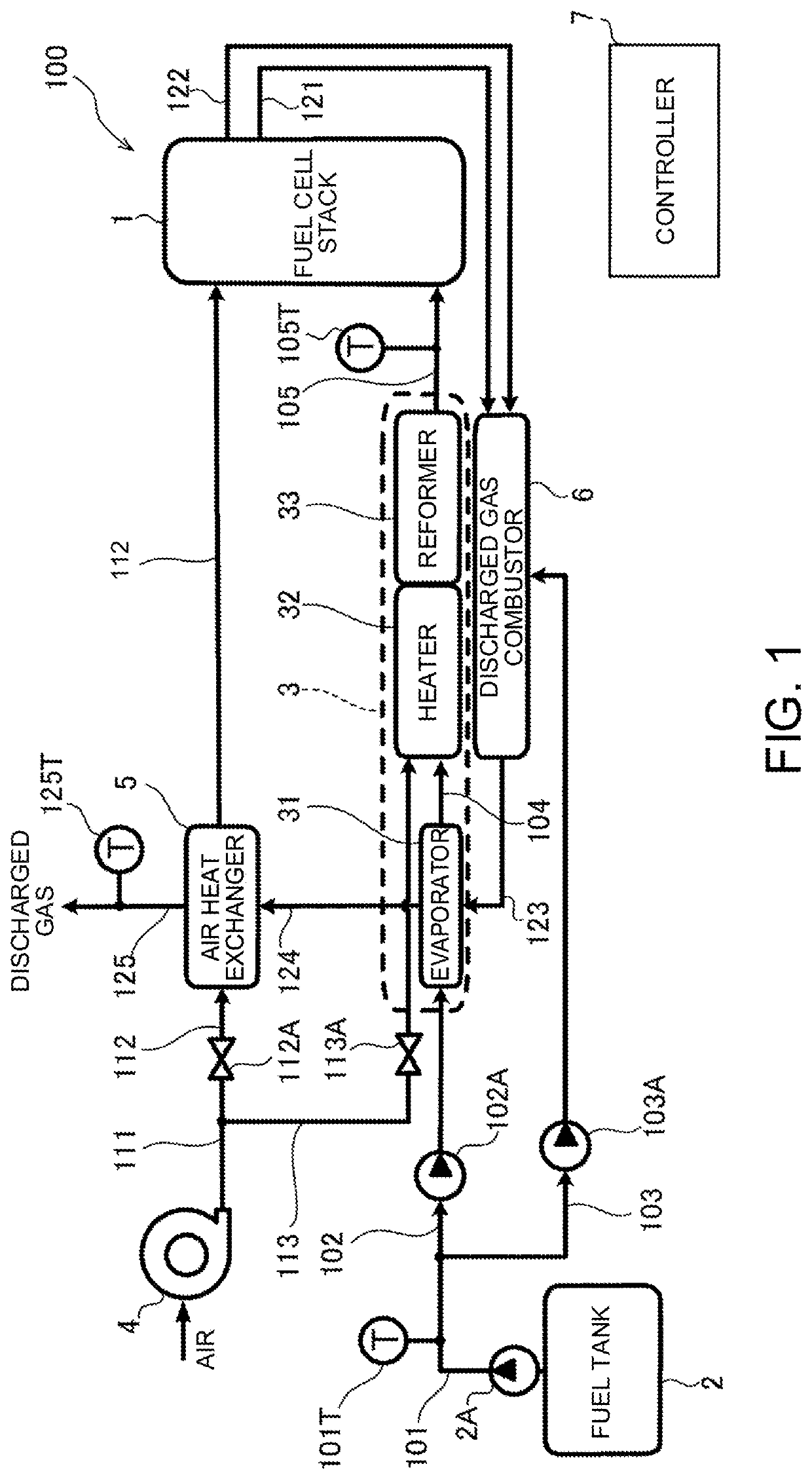
[0026]FIG. 1 is a block diagram illustrating the main configuration of a solid oxide fuel cell (SOFC) system according to the first embodiment.

[0027]A fuel cell stack 1 that is SOFC is made by stacking cells of which each is configured to sandwich an electrolyte layer formed of solid oxide such as ceramic between an anode electrode (fuel electrode) that is supplied with an anode gas (fuel gas) that is fuel and a cathode electrode (air electrode) that is supplied with air containing oxygen as a cathode gas (oxidation gas). The fuel cell stack 1 causes fuel such as hydrogen contained in the anode gas to react with oxygen in the cathode gas to generate electric power, and discharges an anode gas (anode offgas) after the reaction and a cathode gas (cathode offgas) after the reaction.

[0028]A solid oxide fuel cell system 100 (hereinafter, referred to as fuel cell system) including the fuel cell stack 1 is provided with a fuel supply system configured to supply an anode gas to the fuel cel...

second embodiment

[0123]In the first embodiment, there has been explained an example in which the waiting time tair is previously obtained. However, the present invention is not limited to the above. The controller 7 may change the waiting time tair in accordance with the temperature of liquid fuel.

[0124]FIG. 11 is a graph illustrating a relationship between the waiting time tair and a liquid fuel temperature Tfuel. The x-axis indicates the liquid fuel temperature Tfuel and the y-axis indicates the waiting time tair. In addition, the liquid fuel temperature Tfuel is measured by the fuel thermometer 101T.

[0125]If the liquid fuel temperature Tfuel is high, it is not easy to vaporize because fuel is previously heated, and there is shortened a time until the flow rate of fuel gas is higher than the threshold Fth from the start of the supply of fuel to the evaporator 31. For that reason, as illustrated in this drawing, as the liquid fuel temperature Tfuel is higher, the waiting time tair is set shorter.

[0...

third embodiment

[0131]In the first and second embodiments, the process proceeds to the processing of Step S3 when the outlet temperature Tref is higher than the temperature Tref1 at which reforming is possible in the determining step (S2). However, the present invention is not limited to the above. In the determining step (S2), the temperature of the evaporator 31 may be further taken into consideration.

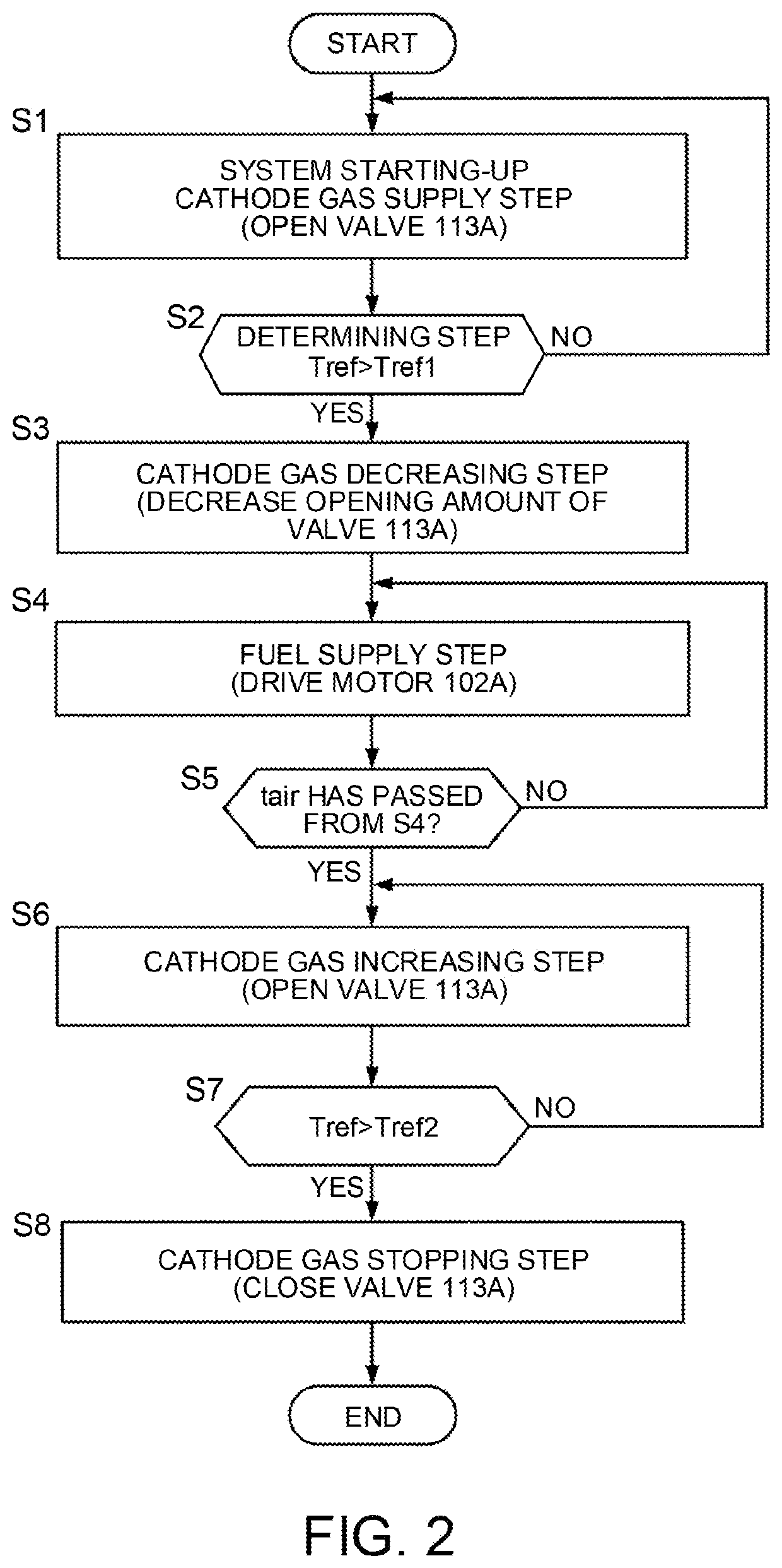
[0132]FIG. 13 is a flowchart illustrating warming control according to the present embodiment. Compared to the flowchart of the warming control illustrated in FIG. 2 according to the first embodiment, this flowchart has the processing of Step S22 that is changed from the processing of Step S2.

[0133]In Step S22, the determining step is performed. The controller 7 determines whether or not the outlet temperature Tref is higher than the temperature Tref1 at which reforming is possible and an evaporator temperature Tvap is higher than a vaporizable temperature Tvap1. In addition, the evaporator temperat...


PUM

PropertyMeasurementUnit
electric poweraaaaaaaaaa
temperatureaaaaaaaaaa
flow rateaaaaaaaaaa

Abstract

According to a control method of controlling a fuel cell system, the fuel cell system including a solid oxide fuel cell that is supplied with an anode gas and a cathode gas to generate electric power, a fuel processor that at least reforms fuel to generate the anode gas and supplies the generated anode gas to the fuel cell, and a combustor that combusts the supplied fuel to perform warming of the fuel processor, the method is conducted when warming is performed at least at starting-up of the system. The method comprising: a cathode gas supply step of supplying the cathode gas to the fuel processor; a determining step of determining whether a temperature of gas passing through the fuel processor is higher than a temperature at which reforming is possible; a cathode gas decreasing step of decreasing a supplied amount of the cathode gas to the fuel processor when it is determined that the temperature of the gas is higher than the temperature at which reforming is possible; and a fuel supply step of supplying the fuel to the fuel processor.

Description

TECHNICAL FIELD[0001]The present invention relates to a fuel cell system control method and a fuel cell system.BACKGROUND ART[0002]It is known that a solid oxide fuel cell (SOFC) is supplied with an anode gas and a cathode gas (air) and operates at a relatively high temperature. A fuel cell system including such the fuel cell is provided with a fuel processor that reforms at least fuel. The fuel processor is warmed up to a temperature at which reforming is possible and then reforms a fuel gas to generate an anode gas.[0003]Because a temperature sensor is provided near the outlet of the fuel processor in order to determine whether the fuel processor reaches the temperature at which reforming is possible, it is necessary to supply a cathode gas before supplying a fuel gas when acquiring the temperature of the fuel processor. It is known that POX (partial oxidation) reforming is performed when the cathode gas is supplied before supplying the fuel gas. One of fuel cell systems warms a f...

Claims


Application Information

Patent Timeline
Patent Type & Authority Applications(United States)
IPC IPC(8): H01M8/04746H01M8/04082H01M8/0432H01M8/0606H01M8/04225H01M8/04701H01M8/04302H01M8/04014H01M8/124
CPCH01M8/04302H01M8/04738H01M8/04753H01M8/04022H01M8/0606H01M2008/1293H01M8/04373H01M8/04201H01M8/04328H01M8/04225H01M8/04776H01M8/0618Y02E60/50
Inventor YAGUCHI, TATSUYACHIKUGO, HAYATO
Owner NISSAN MOTOR CO LTD
Why Eureka
Try Eureka