Image heating apparatus

a heating apparatus and image technology, applied in the field of image heating apparatus, can solve the problems of deteriorating durability, affecting the operation of the fixing apparatus, and affecting the quality of the heating apparatus, so as to achieve the effect of suppressing excessive temperature ris

Inactive Publication Date: 2012-08-07
CANON KK
View PDF5 Cites 0 Cited by
  • Summary
  • Abstract
  • Description
  • Claims
  • Application Information

AI Technical Summary

Benefits of technology

[0014]The present invention has been made in view of the above problem. A purpose of the present invention is to provide an image heating apparatus that can suppress excessive temperature rise in the non-sheet-feeding portion even when warm-up operation starts while the temperature of the non-sheet-feeding portion is higher than that of the sheet-feeding portion.
[0015]Another purpose of the present invention is to provide an image heating apparatus that can suppress excessive temperature rise in the non-sheet-feeding portion while preventing increase in the time of warm-up operation even when warm-up operation starts while the temperature of the non-sheet-feeding portion is higher than that of the sheet-feeding portion.

Problems solved by technology

When the above non-sheet-feeding portion temperature rises to a temperature higher than an allowable temperature, a thermal damage trouble occurs on constituent members of the fixing apparatus, which deteriorates the durability.
Alternatively, in a case where a large size recording material is fed when the non-sheet-feeding portion temperature excessively rises in the fixing apparatus due to successive feeding of small size recording materials, an end portion hot offset and the like may occur due to an excessively high temperature in the non-sheet-feeding portion temperature rise region of the fixing nip portion.
When the temperature control is performed based on the temperature detection element of the sheet-feeding portion at this occasion, the temperature T2 (thin solid line) of the non-sheet-feeding portion becomes higher as shown in FIG. 14, which causes a problem of temperature increase in the non-sheet-feeding portion as described above.
When a detection result of the temperature detection element of the non-sheet-feeding portion indicates that the temperature has reached a temperature Ts at which the safety circuit is activated, there may occur a problem in that the operation of the fixing apparatus is stopped by the activation of the safety circuit at a point A in FIG. 14.
However, the temperature control using the temperature detection element of the non-sheet-feeding portion entails stopping of image forming operation, and accordingly, it takes a longer time to fix an image.
Therefore, the configuration of always performing warm-up operation using the temperature detection element of the non-sheet-feeding portion can avoid the problem caused by the non-sheet-feeding portion temperature rise but still has a problem in that it takes a longer time to fix an image.

Method used


Image

  • Image heating apparatus
  • Image heating apparatus
  • Image heating apparatus

Examples


first embodiment

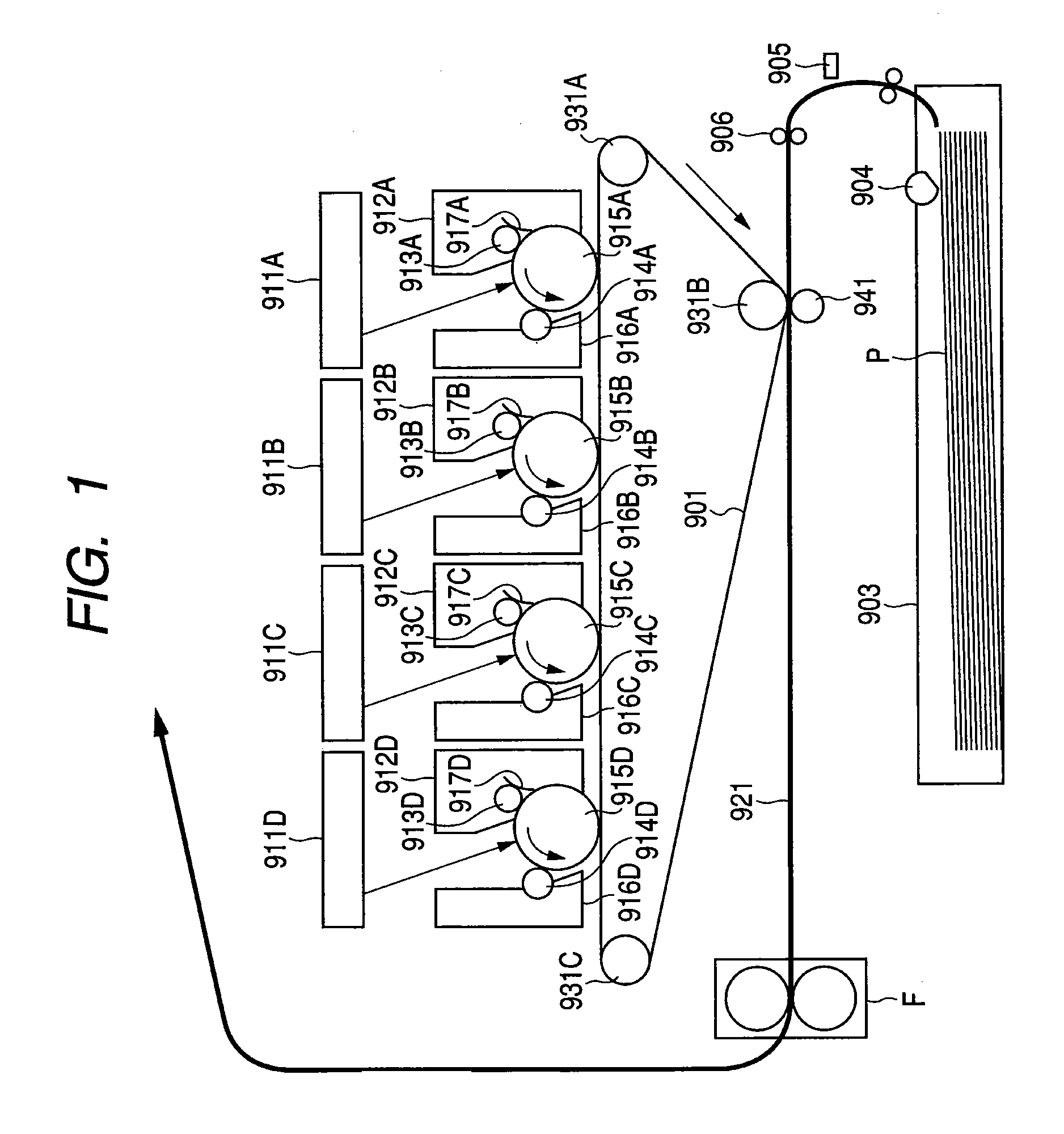
[0033]FIG. 1 shows a schematic cross-sectional diagram showing an image forming apparatus including an image heating apparatus according to the present invention. Examples of the image forming apparatus include a laser beam printer and a copier employing electrophotographic and other recording methods. In the following explanation, a laser beam printer will be described as an example of the image forming apparatus.

[0034]

[0035]The image forming apparatus shown in FIG. 1 is provided with four image forming portions respectively for yellow, magenta, cyan, and black. In the following explanation, reference symbols A, B, C, and D denote portions for yellow, magenta, cyan, and black, respectively.

[0036]Each of the image forming portions includes charge portions 913A, 913B, 913C, 913D for uniformly charging image bearing members, i.e., photosensitive drums 915A, 915B, 915C, 915D, to a predetermined potential. The photosensitive drums 915A, 915B, 915C, 915D rotate in a counter-clockwise dir...

second embodiment

[0064]In the second embodiment, even when the temperature detected by the end portion thermistor is higher than the temperature detected by the center portion thermistor, the temperature control is performed based on the temperature detected by the center portion thermistor as long as the temperature detected by the center portion thermistor is equal to or more than the target temperature.

Temperature Control of Fixing Apparatus According to the Present Embodiment

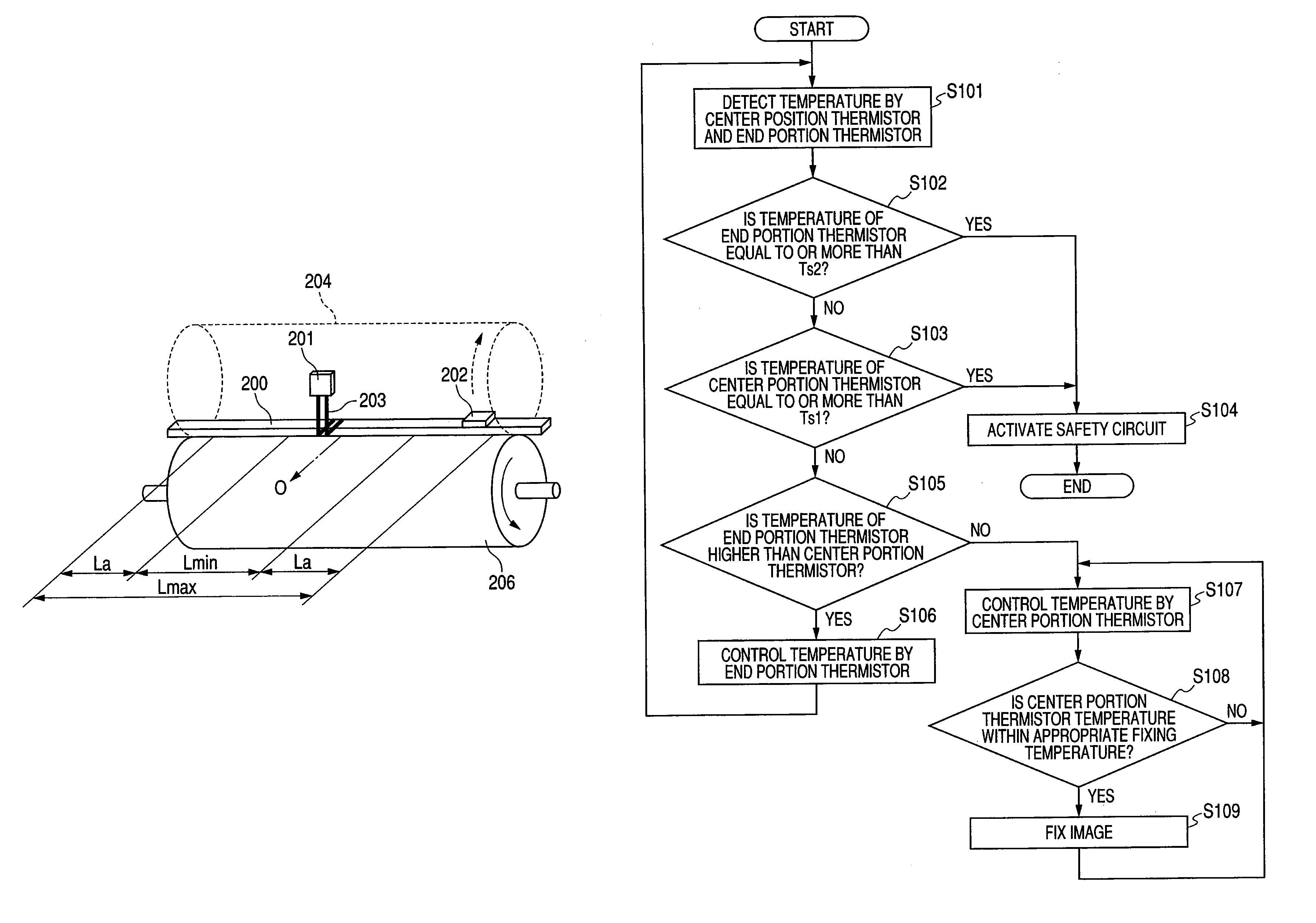
[0065]FIG. 7 is a flowchart showing print operation control according to the present embodiment. Since the structures of the image forming apparatus and the fixing apparatus F are the same as those of the first embodiment, the description thereof is omitted. In the following explanation, the same elements are denoted by the same reference numerals of FIG. 1 to FIG. 4.

[0066]The print operation control is executed by the CPU 301 of the control circuit unit based on the outputs of the center portion thermistor 201 and the end p...

third embodiment

[0074]In the third embodiment, when the temperature control is performed based on the temperature detected by the center portion thermistor, the target temperature is switched.

Temperature Control of Fixing Apparatus According to the Present Embodiment

[0075]FIG. 9 is a flowchart showing print operation control according to the third embodiment. Since the structures of the image forming apparatus and the fixing apparatus are the same as those of the first embodiment, the description thereof is omitted. In the following explanation, the same elements are denoted by the same reference numerals of FIG. 1 to FIG. 4.

[0076]The print operation control is executed by the CPU 301 of the control circuit unit based on the outputs of the center portion thermistor 201 and the end portion thermistor 202.

[0077]When the print operation starts, the CPU 301 uses the center portion thermistor 201 and the end portion thermistor 202 to detect the temperatures at the center portion and the end portion (S30...


PUM


Abstract

The non-sheet-feeding portion temperature rise is reduced during warm-up operation of an image heating apparatus, the time needed for the warm-up operation is reduced, and the accuracy of the image fixing operation is improved. When a CPU determines that a temperature detected by an end portion thermistor is higher than a temperature detected by a center portion thermistor, the CPU controls the temperature of a fixing heater based on a detection result of the end portion thermistor. When the CPU determines that the temperature detected by the end portion thermistor is equal to or less than the temperature detected by the center portion thermistor, the CPU controls the temperature of the fixing heater based on a detection result of the center portion thermistor.

Description

BACKGROUND OF THE INVENTION[0001]1. Field of the Invention[0002]The present invention relates to an image heating apparatus preferably used as a toner image fixing apparatus of an image forming apparatus such as a copier, a laser beam printer, and a facsimile machine.[0003]The image heating apparatus referred to herein includes not only a fixing apparatus for heating and fixing an unfixed image onto a recording material as a permanent image but also an apparatus for temporarily fixing an unfixed image onto a recording material and an apparatus for improving the quality of the surface nature of image such as gloss by reheating a recording material carrying an image thereon.[0004]2. Description of the Related Art[0005]There is an image forming apparatus in which an unfixed toner image corresponding to image information as an object is formed and borne on a surface of a recording material with toner (developer) by direct or indirect transfer methods by means of an appropriate one of im...

Claims


Application Information

Patent Timeline
Patent Type & Authority Patents(United States)
IPC IPC(8): G03G15/20
CPCG03G15/2042
Inventor OHASHI, EIJIRO
Owner CANON KK
Why Eureka
Try Eureka