Fixing device and image forming apparatus
a technology of fixing device and image forming apparatus, which is applied in the direction of electrographic process apparatus, instruments, optics, etc., can solve the problems of deteriorating the responsiveness of the temperature detector with respect to a temperature change in the heat source or the like, and achieves the effects of suppressing excessive temperature rise, reducing heat conduction, and reducing heat conduction
- Summary
- Abstract
- Description
- Claims
- Application Information
AI Technical Summary
Benefits of technology
Problems solved by technology
Method used
Image
Examples
exemplary embodiment 1
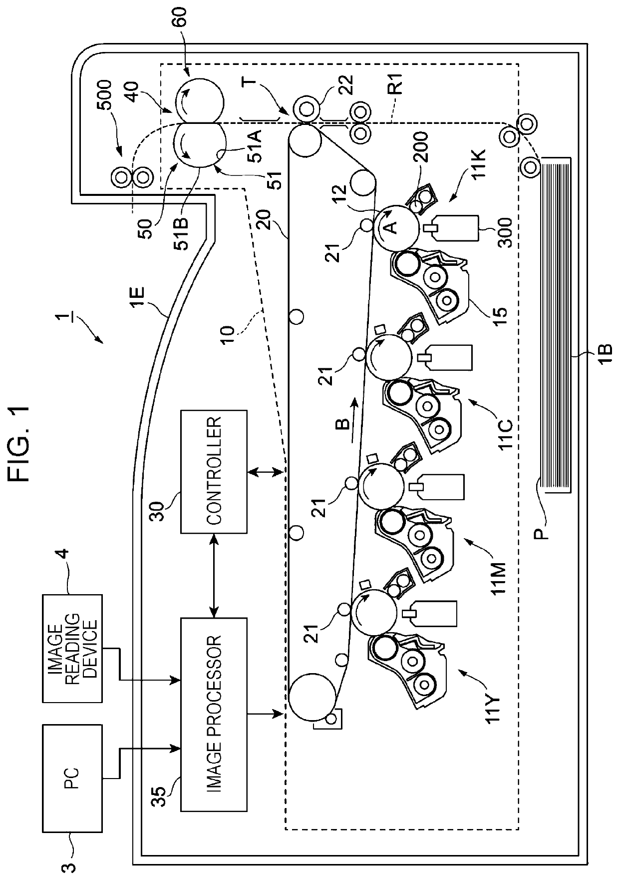
[0024]FIG. 1 illustrates an overall configuration of an image forming apparatus 1.
[0025]The image forming apparatus 1 is a so-called tandem-type color printer.
[0026]The image forming apparatus 1 includes an image forming section 10 as an exemplary image forming device. The image forming section 10 forms an image on a sheet P as an exemplary recording material in accordance with pieces of image data for different colors.
[0027]The image forming apparatus 1 further includes a controller 30 and an image processor 35.
[0028]The controller 30 controls relevant functional elements included in the image forming apparatus 1.
[0029]The image processor 35 processes the pieces of image data received from a device such as a personal computer (PC) 3 or an image reading device 4.
[0030]The image forming section 10 includes four image forming units 11Y, 11M, 11C, and 11K (hereinafter also generally denoted as “image forming units 11”) arranged at intervals and in parallel.
[0031]The image forming units...
second exemplary embodiment
[0114]A second exemplary embodiment of the present disclosure will now be described. Elements that are the same as those described in the first exemplary embodiment are denoted by corresponding ones of the reference numerals, and detailed description of those elements is omitted herein.
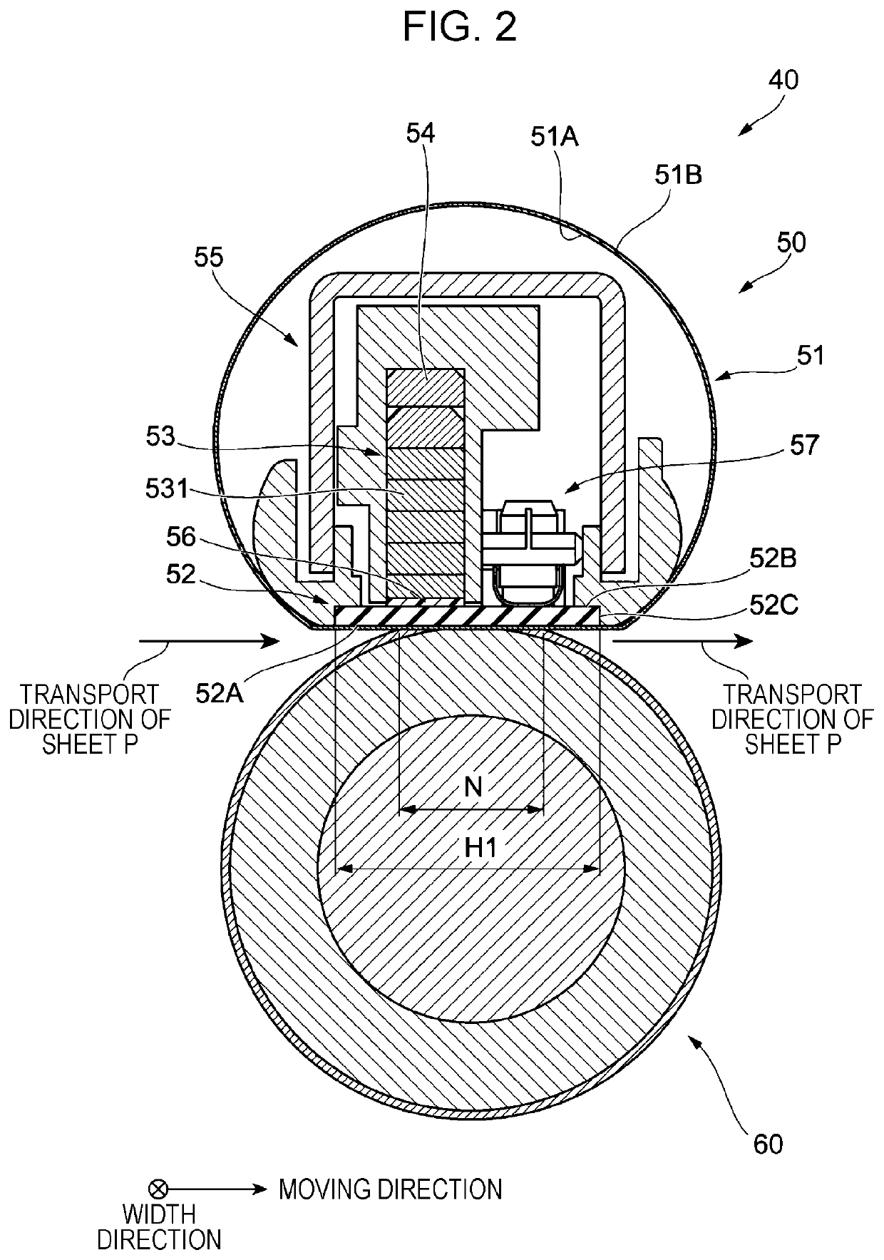
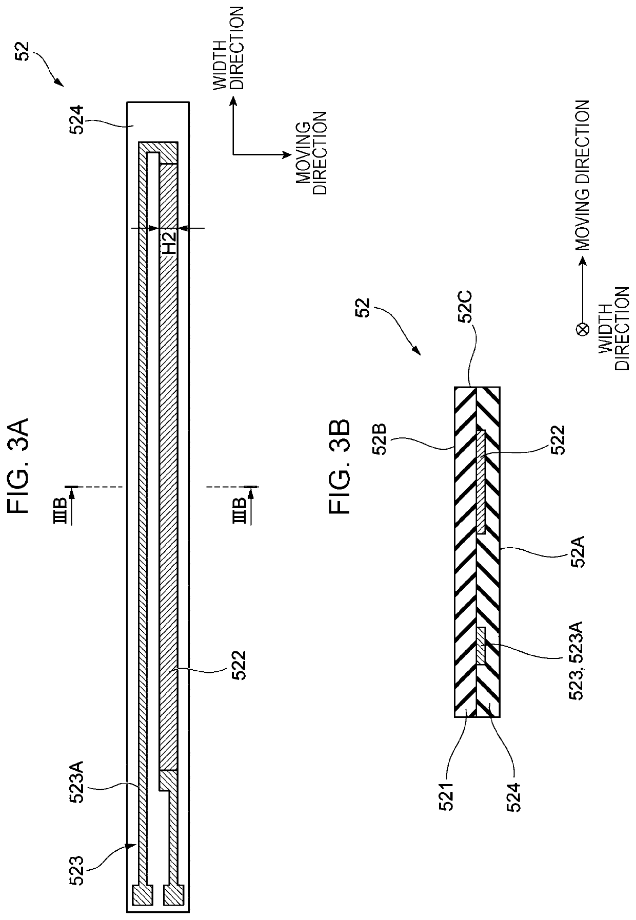
[0115]FIGS. 7 and 8 illustrate an arrangement of the heat source 52, the high-thermal-conductivity portion 53, the low-thermal-conductivity portion 56, and the temperature sensors 57 according to the second exemplary embodiment. FIG. 7 is a plan view of the heat source 52, the high-thermal-conductivity portion 53, the low-thermal-conductivity portion 56, and the temperature sensors 57 seen in the direction of stacking of the high-thermal-conductivity portion 53 and so forth on the heat source 52. FIG. 8 is a sectional view of a width-direction central portion of the fixing device 40, taken along line VIII-VIII illustrated in FIG. 7.
[0116]In FIG. 7, the base layer 521 of the heat source 52 is not illus...
third exemplary embodiment
[0128]A third exemplary embodiment of the present disclosure will now be described. Elements that are the same as those described in the first exemplary embodiment are denoted by corresponding ones of the reference numerals, and detailed description of those elements is omitted herein.
[0129]FIGS. 9 and 10 illustrate an arrangement of the heat source 52, the high-thermal-conductivity portion 53, the low-thermal-conductivity portion 56, and the temperature sensors 57 according to the third exemplary embodiment. FIG. 9 is a plan view of the heat source 52, the high-thermal-conductivity portion 53, the low-thermal-conductivity portion 56, and the temperature sensors 57 seen in the direction of stacking of the high-thermal-conductivity portion 53 and so forth on the heat source 52. FIG. 10 is a sectional view of a width-direction central portion of the fixing device 40, taken along line X-X illustrated in FIG. 9.
[0130]In FIG. 9, the base layer 521 of the heat source 52 is not illustrated...
PUM
| Property | Measurement | Unit |
|---|---|---|
| thermal-conductivity | aaaaa | aaaaa |
| thermal conductivity | aaaaa | aaaaa |
| temperature | aaaaa | aaaaa |
Abstract
Description
Claims
Application Information
 - R&D
- Intellectual Property
- Life Sciences
- Materials
- Tech Scout
- Unparalleled Data Quality
- Higher Quality Content
- 60% Fewer Hallucinations
Browse by: Latest US Patents, China's latest patents, Technical Efficacy Thesaurus, Application Domain, Technology Topic, Popular Technical Reports.
© 2025 PatSnap. All rights reserved.Legal|Privacy policy|Modern Slavery Act Transparency Statement|Sitemap|About US| Contact US: help@patsnap.com


