Pulse wave detection device, image analysis device, and biometric information generation system

a technology of image analysis and detection device, which is applied in the direction of angiography, diagnostics using spectroscopy, instruments, etc., can solve the problems of difficult to accurately detect pulse waves, and achieve the effect of accurately detecting pulse waves of living bodies

Active Publication Date: 2021-07-20
SHARP KK
View PDF23 Cites 1 Cited by
  • Summary
  • Abstract
  • Description
  • Claims
  • Application Information

AI Technical Summary

Problems solved by technology

However, with a contact style pulse wave detection device, it is difficult to accurately detect the pulse waves because a subject to be measured becomes conscious of the measurement and deformation of the blood vessel occurs due to a measurement point of the subject to be measured making contact with the pulse wave detection device.

Method used


Image

  • Pulse wave detection device, image analysis device, and biometric information generation system
  • Pulse wave detection device, image analysis device, and biometric information generation system
  • Pulse wave detection device, image analysis device, and biometric information generation system

Examples


first embodiment

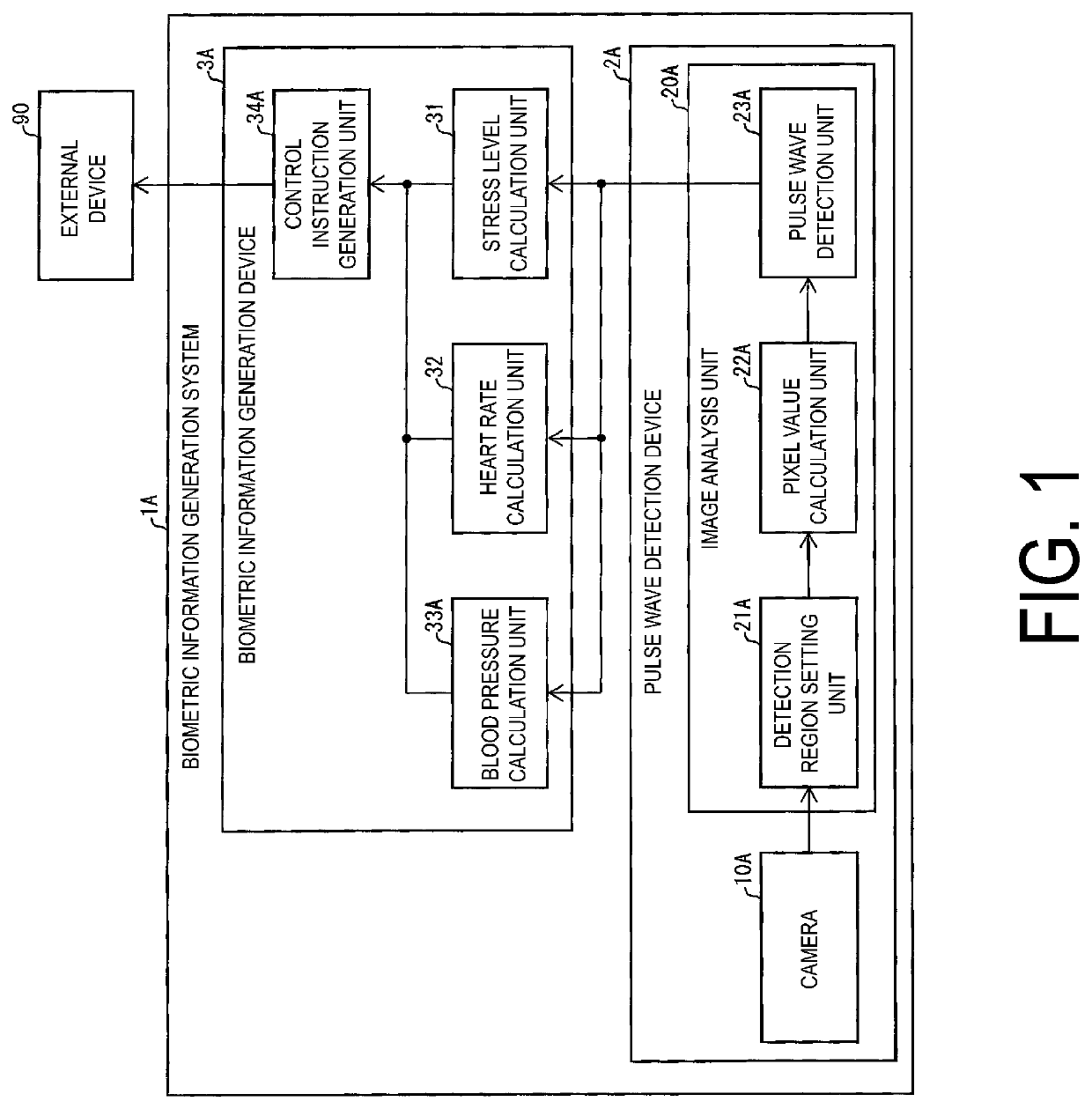
[0033]A biometric information generation system 1A according to a first embodiment of the present disclosure will be described in detail with reference to FIGS. 1 to 6.

Configuration of Biometric Information Generation System 1A

[0034]The configuration of the biometric information generation system 1A will be described with reference to FIG. 1. FIG. 1 is a block diagram illustrating the configuration of a main portion of the biometric information generation system 1A.

[0035]As illustrated in FIG. 1, the biometric information generation system 1A includes a pulse wave detection device 2A and a biometric information generation device 3A.

Pulse Wave Detection Device 2A

[0036]As illustrated in FIG. 1, the pulse wave detection device 2A includes a camera (imaging unit, imaging device) 10A and an image analysis unit (image analysis device) 20A.
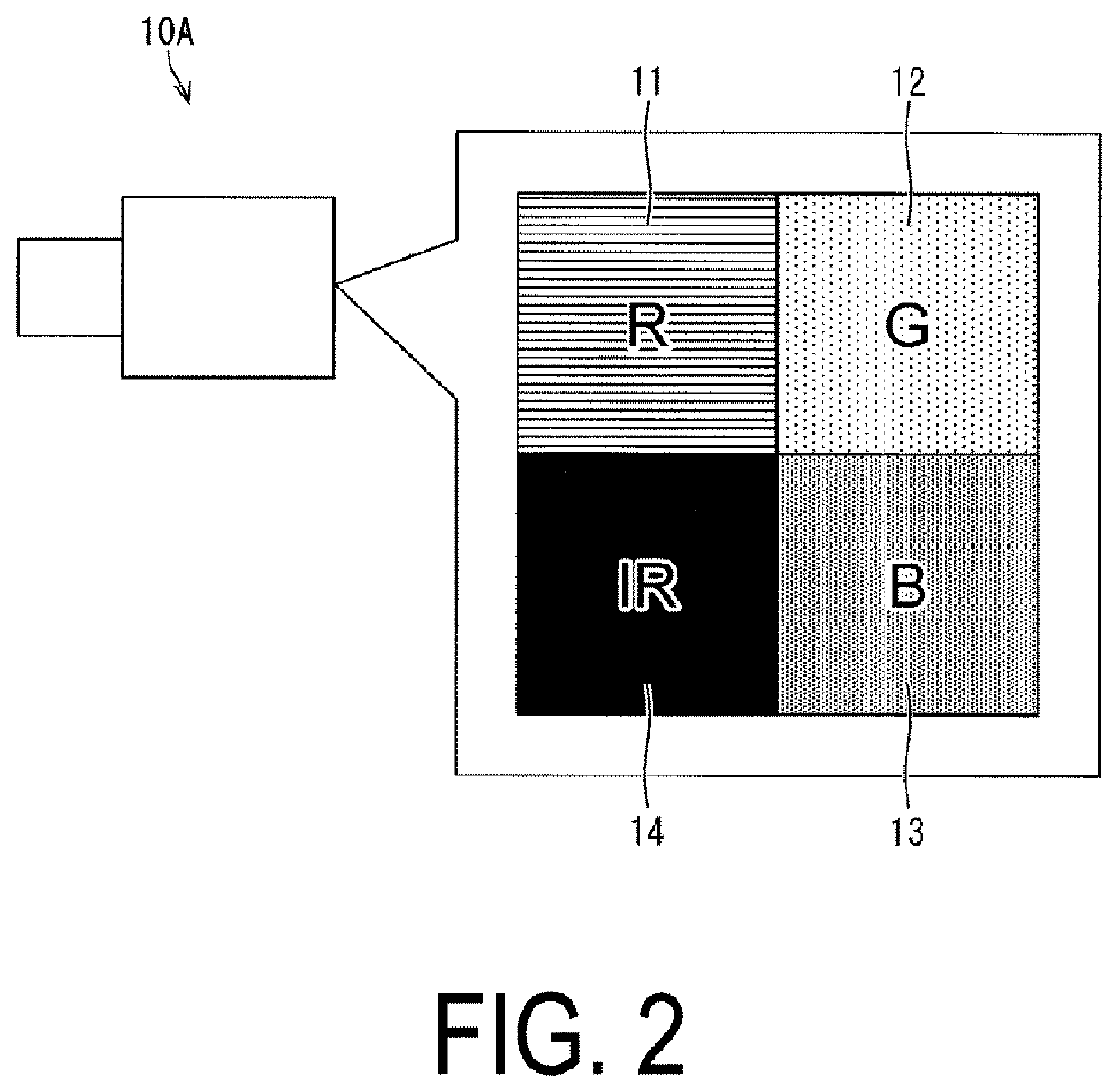
Camera 10A

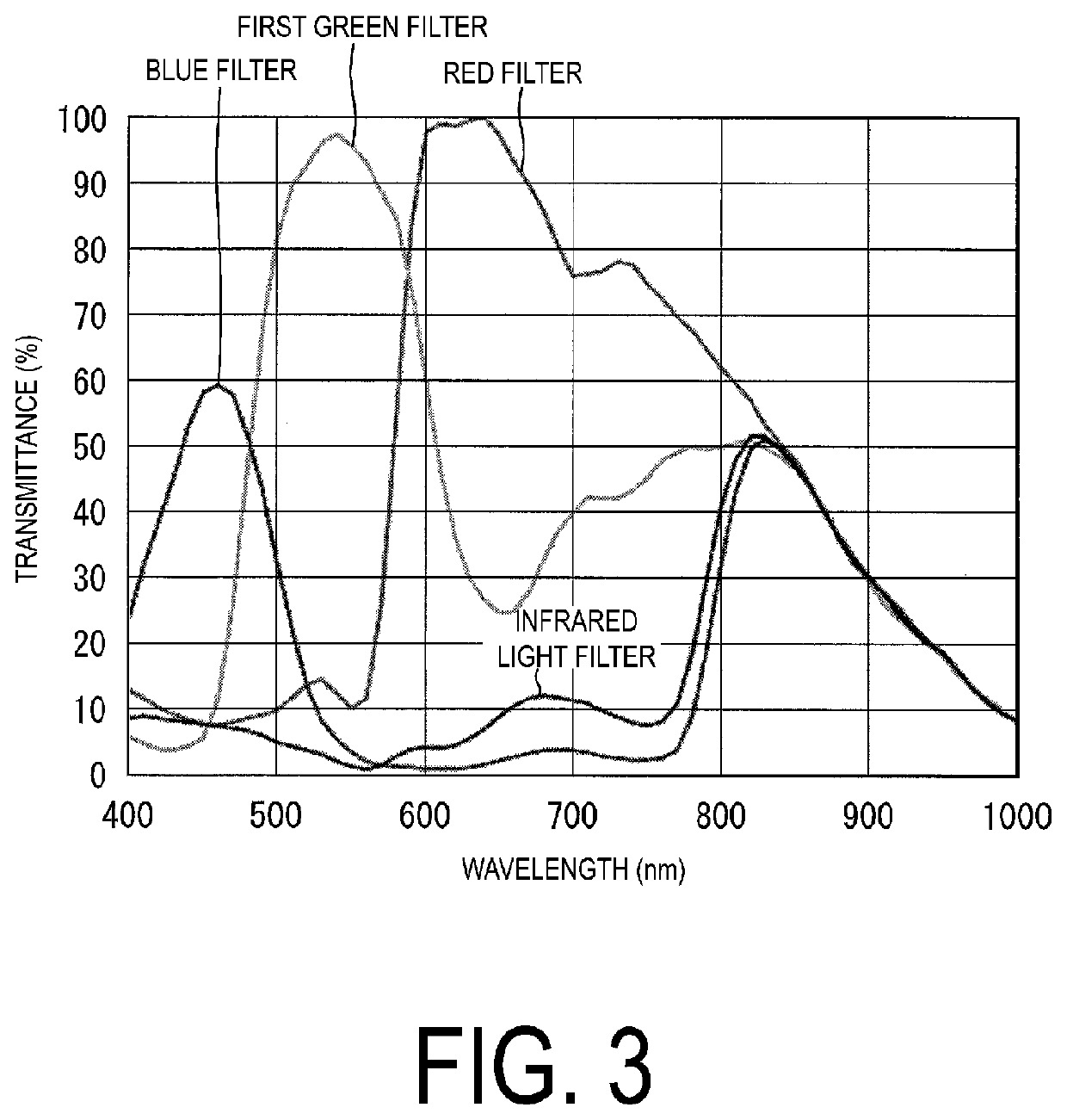
[0037]The camera 10A will be described with reference to FIG. 2. FIG. 2 is a schematic diagram illustrating the configuration of the camera 10...

modification 1

[0078]Next, a biometric information generation system 1B as a modification of the biometric information generation system 1A will be described. Note that, for convenience of description, components having the same function as that of components described in the above embodiment are designated by the same reference numerals, and the descriptions of these components will be omitted.

Configuration of Biological Information Generation System 1B

[0079]The configuration of the biometric information generation system1B will be described with reference to FIG. 7. FIG. 7 is a block diagram illustrating the configuration of a main portion of the biometric information generation system 1B.

[0080]As illustrated in FIG. 7, the biometric information generation system 1B includes a pulse wave detection device 2B and a biometric information generation device 3B in place of the pulse wave detection device 2A and the biometric information generation device 3A in the biometric information generation syst...

modification 2

[0092]Next, a biometric information generation system 1C as another modification of the biometric information generation system 1A will be described. Note that, for convenience of description, components having the same function as that of components described in the above embodiment are designated by the same reference numerals, and the descriptions of these components will be omitted.

Configuration of Biometric Information Generation System 1C

[0093]The configuration of the biometric information generation system 1C will be described with reference to FIG. 8. FIG. 8 is a block diagram illustrating the configuration of a main portion of the biometric information generation system 1C.

[0094]As illustrated in FIG. 8, the biometric information generation system 1C includes a biometric information generation device 3C in place of the biometric information generation device 3A in the biometric information generation system 1A. In addition to the configuration of the biometric information g...


PUM

PropertyMeasurementUnit
red visible light wavelength rangeaaaaaaaaaa
wavelengthaaaaaaaaaa

Abstract

Pulse waves of a living body are detected with high accuracy. A pulse wave detection device includes a camera configured to capture an image of the living body a plurality of times through a first green filter and an infrared light filter having light transmission characteristics in a near-infrared light wavelength range within a wavelength range where a light absorption coefficient of oxidized hemoglobin is greater than a light absorption coefficient of reduced hemoglobin, and an image analysis unit configured to analyze a plurality of images of the living body captured by the camera and to detect the pulse waves of the living body. The image analysis unit is configured to detect the pulse waves by detecting a change in intensity of light in the near-infrared light wavelength range indicated by the plurality of images.

Description

TECHNICAL FIELD[0001]The following disclosure relates to a pulse wave detection device and an image analysis device configured to detect pulse waves of a living body, and a biometric information generation system configured to generate biometric information of the living body on the basis of the pulse waves of the living body detected by the pulse wave detection device.BACKGROUND ART[0002]Pulse wave detection devices configured to detect pulse waves that refer to waveforms representing blood vessel beats associated with blood ejection of the heart are known. Biometric information, such as stress levels and blood pressure, can be obtained from the pulse waves detected by the above-mentioned pulse wave detection device.[0003]A contact type pulse wave detection device is known as a pulse wave detection device. However, with a contact style pulse wave detection device, it is difficult to accurately detect the pulse waves because a subject to be measured becomes conscious of the measurem...

Claims


Application Information

Patent Timeline
Patent Type & Authority Patents(United States)
IPC IPC(8): A61B5/021A61B5/024G06K9/00G06T7/00A61K38/42G06V10/143G06V40/145
CPCA61B5/02108A61B5/02444G06K9/00906G06T7/0012A61K38/42A61B2562/0219A61B5/0075A61B5/165A61B5/14542A61B5/1032A61B5/0077A61B5/02416A61B5/7225A61B5/318A61B5/352G06V40/45G06V40/15G06V10/143G06V40/145
Inventor ONISHI, JUNYAADACHI, YOSHIHISAOKUMURA, TETSUYANUNOKAWA, TAKASHIOGAWA, RIEKO
Owner SHARP KK
Why Eureka
Try Eureka