Surround view system having an adapted projection surface

a projection surface and projection surface technology, applied in the field of projection surface, can solve problems such as distortion in an altered virtual perspectiv

Active Publication Date: 2022-08-09
CONTI TEMIC MICROELECTRONIC GMBH
View PDF40 Cites 0 Cited by
  • Summary
  • Abstract
  • Description
  • Claims
  • Application Information

AI Technical Summary

Problems solved by technology

During this transformation, raised objects such as, for example, other vehicles, posts or flower tubs can, due to the respective perspective during the prod...

Method used


Image

  • Surround view system having an adapted projection surface
  • Surround view system having an adapted projection surface

Examples


Embodiment Construction

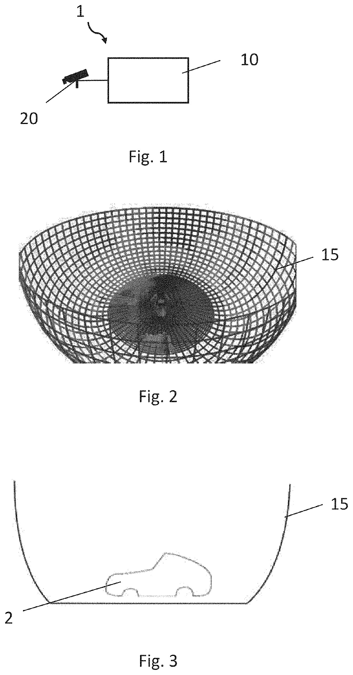
[0043]FIG. 1 shows a block diagram of a surround view system 1 for a vehicle according to an embodiment of the invention. The surround view system 1 comprises a detection unit 20 and an evaluation unit 10. The detection unit 20 can detect data relating to the surroundings of a vehicle. For example, the detection unit 20 can comprise one camera or multiple cameras. Alternatively or in addition, the detection unit 20 can also comprise a lidar, a radar or an ultrasonic sensor, a laser scanner or a combination hereof. In particular, objects around the vehicle can be detected by the detection unit 20.

[0044]The evaluation unit 10 can merge the data relating to the surroundings detected by the detection unit 20 into a surround view image and display them for the driver of a vehicle, for example on a display unit. For the illustration of the surround view image for the driver, the detected data relating to the surroundings can be projected onto a projection surface. This projection surface ...


PUM


Abstract

A surround view system for a vehicle includes a detection unit and an evaluation unit. The detection unit is designed to detect data relating to the surroundings. The evaluation unit is designed to identify an object in the detected surroundings data and to determine the 3D shape of this object. The evaluation unit is additionally designed to add the determined 3D shape to a projection surface of the surround view system to produce a modified projection surface. The evaluation unit is designed to project the surroundings data onto the modified projection surface.

Description

FIELD OF THE INVENTION[0001]The invention relates to a surround view system for a vehicle, a vehicle having such a surround view system, a method for adapting a projection surface of a surround view system, a program item and a computer-readable medium.BACKGROUND INFORMATION[0002]Vehicles are increasingly being equipped with driver assistance systems which assist the driver during the performance of driving maneuvers. These driver assistance systems partially contain surround view systems which allow the driver of the vehicle to display the vehicle environment. Such surround view systems have one or more vehicle cameras which detect real images of the vehicle environment and are subsequently merged by a data processing unit of the surround view system into an image of the vehicle environment. The image of the vehicle environment is subsequently displayed to the driver on a display unit.[0003]To this end, the real images of the vehicle environment obtained by the cameras of the surro...

Claims


Application Information

Patent Timeline
IPC IPC(8): G06V20/58G06V20/64
CPCG06V20/58G06V20/64
Inventor BUERKER, MARTINGLOGER, CHARLOTTEPANAKOS, ANDREASKITTMANN, FRANK
Owner CONTI TEMIC MICROELECTRONIC GMBH
Why Eureka
Try Eureka