Method of modeling of faulting and fracturing in the earth

a faulting and fracture technology, applied in the field of earth faulting fracture modeling, can solve problems such as and achieve the effect of speeding up computation time and facilitating the conditioning step

Inactive Publication Date: 2006-04-18
CONOCO INC +1
View PDF15 Cites 13 Cited by
  • Summary
  • Abstract
  • Description
  • Claims
  • Application Information

AI Technical Summary

Benefits of technology

[0018]The computational method used in solving for the deformation is a modified over-relaxation approach. In the basic over-relaxation method, equilibrium is reached by moving each node distance proportional to the force acting on the node. The constant of proportionality is called the over-relaxation constant and optimal methods for selecting it are known. In each relaxation cycle, each node is moved and the relaxation cycles repeated until no node is moved further than a threshold distance, which is called the relaxation threshold. In the present invention, the over-relaxation is concentrated in those nodes where the greatest movement occurs. This significantly speeds up the computation time.
[0019]A novel aspect of the invention is the conditioning of the model. In the real world, the interpretation of the subsurface structure starts with observations of large scale fracturing and faulting. In one aspect of the invention, based upon the observed large-scale deformations, the user derives an initial geometry of the unfaulted material. Since it is clearly desirable that the end result of applying stresses to the model should at least duplicate the observed large-scale deformations, the model is weakened at the reconstructed fault positions so that upon application of the stresses, there will be a predisposition to produce the observed large-scale fractures and faults. The conditioning step is made easier in the present invention by use of the graphical user interface.

Problems solved by technology

This significantly speeds up the computation time.

Method used


Image

  • Method of modeling of faulting and fracturing in the earth
  • Method of modeling of faulting and fracturing in the earth
  • Method of modeling of faulting and fracturing in the earth

Examples


Embodiment Construction

An Overview of the Invention

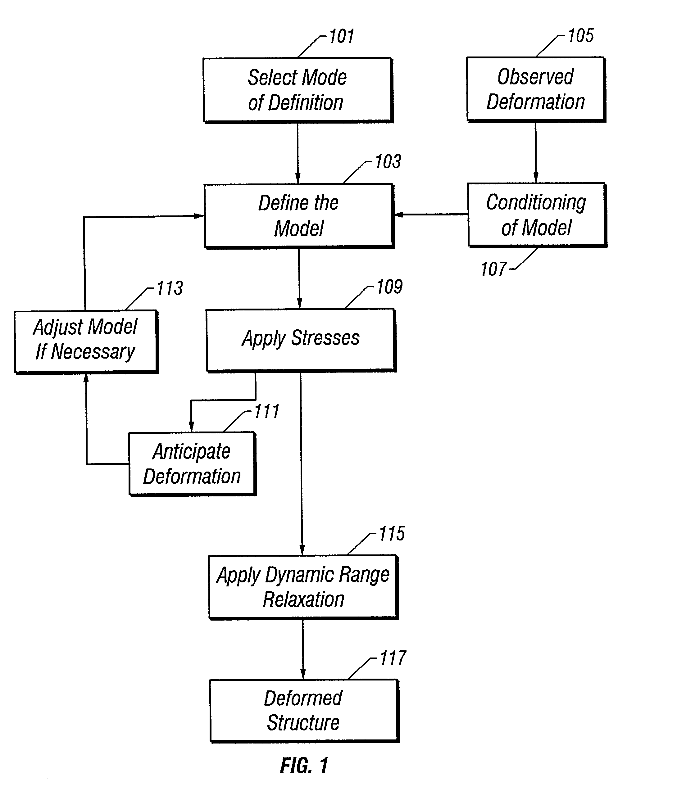
[0036]Turning now to FIG. 1, a flow chart of the major steps of the present invention is depicted. The first step in the invention is to select a mode of definition of the subsurface 101. This is described further below in reference to FIGS. 2a–2b. This step defines the boundaries of the model and the nodal configuration therein. The mode of definition may be aerial, cross-sectional or 3-D. Within the model, a plurality of interconnected nodes that characterize the geometry of the model are defined. In a preferred embodiment of the invention, the nodal pattern is a regular triangular lattice, although other patterns, such as a random lattice, may also be used. The user may also specify the number of nodes in and the aspect ratio of the model. This is conveniently done using the GUI. The GUI is discussed below in reference to FIGS. 6–13.

[0037]Within the framework of the nodal geometry defined at 101, the material properties of model are input 103. The node...


PUM


Abstract

A Graphical User Interface for displaying and manipulating a model of interconnected nodes that simulates fracturing and faulting in a subsurface volume of the earth. The model incorporates a dynamic range relaxation algorithm.

Description

[0001]This application is a divisional of U.S. patent application Ser. No. 09 / 542,307 filed on Apr. 4, 2000, now U.S. Pat. No. 6,370,491.BACKGROUND OF THE INVENTION[0002]1. Field of the Invention[0003]The invention relates to a method for forward modeling the spatial distribution faults and fractures in a geologic formation.[0004]2. Background of the Invention[0005]The prediction of faulting and fracturing is very important in oil and gas exploration and production. Seismic data is often used to find faults that bound or delineate hydrocarbon reservoirs. However, due to the limited resolution of seismic data, the details of the faulting in the subsurface may not be determinable.[0006]Knowledge of the distribution of the fractures in a geologic formation is of great importance first for optimizing the location and the spacing between the wells that are to be drilled through an oil formation. Furthermore, the geometry of the fracture network conditions influences the displacement of f...

Claims


Application Information

Patent Timeline
Patent Type & Authority Patents(United States)
IPC IPC(8): G06G7/48G06F7/64G01V1/28G06FG06F7/60G06F17/10
CPCG01V1/282G01V1/288G01V2210/66
Inventor MALTHE-SORENSSEN, ANDERSWALMANN, THOMASJOSSANG, TORSTEINWAGNER, GERIFEDER, JENSHARDY, HUMPHREY H.
Owner CONOCO INC
Why Eureka
Try Eureka