Method for machining a workpiece by means of a chip-removing tool on a numerically-controlled machine tool

a numerically controlled machine tool and chip removal technology, applied in the direction of electric programme control, program control, instruments, etc., can solve the problems of reducing the surface quality of the workpiece that is to be produced, the distribution of supporting points within the individual tool path is often unfavourable, and the position of individual supporting points is not always precise. , to achieve the effect of improving the machining result, improving the course of the tool path, and making the course more precis

Inactive Publication Date: 2017-11-30
P&L GMBH & CO KG
View PDF2 Cites 3 Cited by
  • Summary
  • Abstract
  • Description
  • Claims
  • Application Information

AI Technical Summary

Benefits of technology

[0020]Since the CNC controller always knows the position of the tool relative to the desired surface data during the machining procedure, said CNC controller can add additional supporting points moreover at particular sites, for example singularities such as edges or, since the geometry of forms is usually described by means of many individual partial surfaces that adjoin one another, at the transition from one partial surface to the next partial surface. Consequently, it is possible depending upon the local geometry of the desired surface of the workpiece, to add supporting points if that improves the course of the tool path in the milling program, in other words makes the course more precise. It is possible to improve the machining result not only for the position of an additional supporting point but also for

Problems solved by technology

The position of the individual supporting points unfortunately is not always precise even in the case of modern computer-aided manufacturing (“CAM”) systems.
This leads to inaccuracies and a reduction of the surface quality of the workpiece that is to be produced.
Moreover, the distribution of the supporting points within the individual tool paths is frequently unfavourable.
If the number of supporting points in a region is considerably different or if said supporting points are not precisely calculated, depending upon the algorithms that are used, deviations for the

Method used


Image

  • Method for machining a workpiece by means of a chip-removing tool on a numerically-controlled machine tool
  • Method for machining a workpiece by means of a chip-removing tool on a numerically-controlled machine tool
  • Method for machining a workpiece by means of a chip-removing tool on a numerically-controlled machine tool

Examples


Embodiment Construction

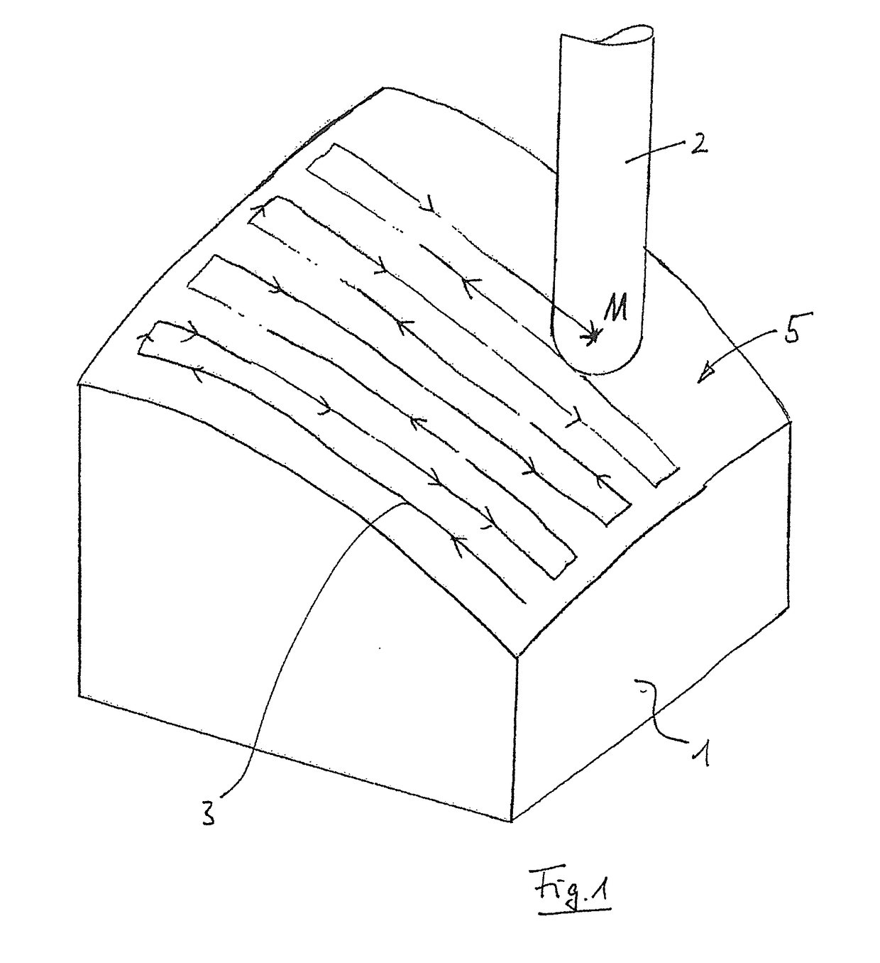
[0027]FIG. 1 illustrates the schematic view of a workpiece 1 that is machined using a spherical tool 2. The centre point path of this tool centre point M is described for the machining procedure in the machining program and said tool centre point M, as is illustrated in FIG. 1, ensures that the tool 2 moves in a line-shaped path on the surface of the workpiece 1. In the geometric data relating to the workpiece (the form), the desired surface of the workpiece 1 is contained as free-form surface data. This geometric information can be transmitted in a standard format, for example STEP, to the controller as a file. Moreover, for the machining procedure, a numerically-controlled program is transmitted to the controller and said numerically-controlled program describes the line-shaped tool path of the spherical tool 2 relative to the form by means of a sequence of supporting points.

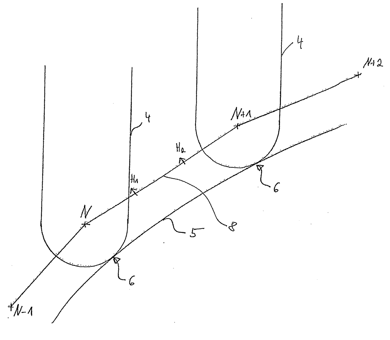
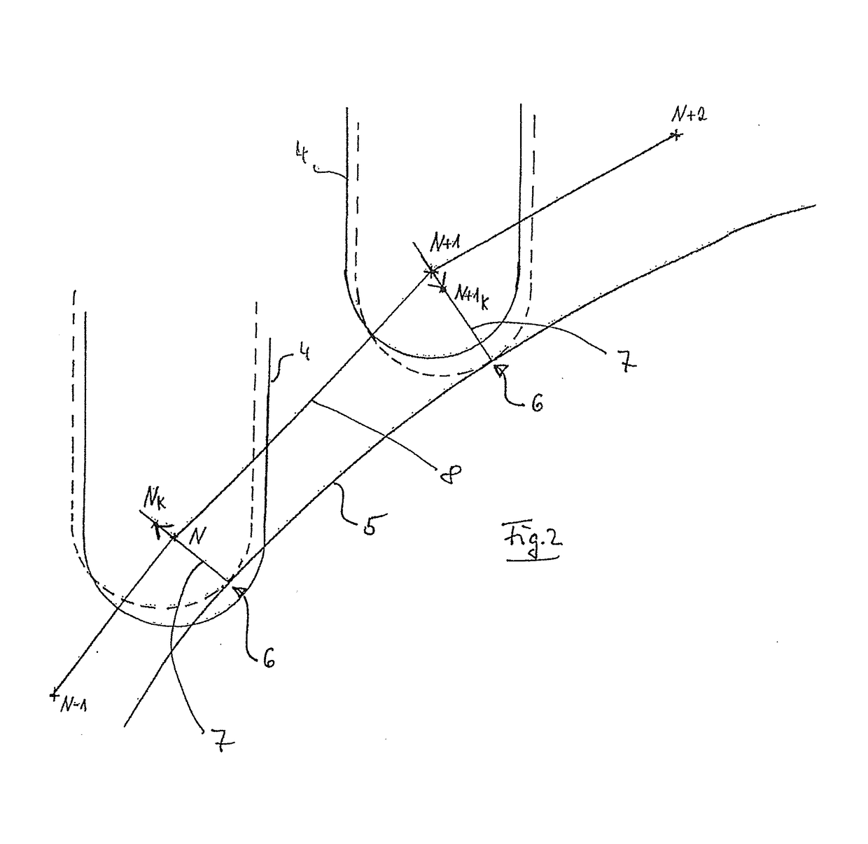
[0028]FIG. 2 is illustrated as a 2D view of a section of the tool path 3 relative to the desired surface of...


PUM


Abstract

The invention relates to a method for machining a workpiece by means of a chip-removing tool on a numerically-controlled machine tool, in which the tool is moved relative to the workpiece along tool paths that are formed by means of a sequence of supporting points N, wherein the bounding volume that is produced during the rotation of the tool essentially comprises a point contact in a point of contact with the desired surface of the workpiece when machining the workpiece, and that in addition to the data relating to the supporting point N the data relating to the respective point of contact of the bounding volume with the desired surface of the workpiece are determined and that the tool path is optimized on the basis of the data relating to the point of contact.

Description

FIELD OF THE INVENTION[0001]The invention relates to a method for machining a workpiece by means of a chip-removing tool on a numerically-controlled machine tool, in which the tool is moved relative to the workpiece along tool paths, for example lines that are formed by means of a sequence of supporting points, wherein the bounding volume that is produced during the rotation of the tool essentially comprises a point contact in a point of contact with the surface of the workpiece when machining the workpiece.BACKGROUND OF THE INVENTION[0002]A milling method using spherical machining tools is frequently used to produce free-form surfaces for example in moulds for the production of synthetic material parts. There is only one point contact between the surface of the workpiece and the bounding volume that is produced by means of the rotation of the tool. In order to provide the surface of the workpiece with a specific measurement and surface quality, the tool is usually moved in lines ov...

Claims


Application Information

Patent Timeline
IPC IPC(8): G05B19/4097B23C5/10
CPCG05B19/4097G05B2219/35012G05B2219/49047B23C5/1009G05B19/4099G05B19/4103G05B2219/50334
Inventor RODERS, JURGEN
Owner P&L GMBH & CO KG
Why Eureka
Try Eureka