Lachrymal plugs and methods for setting same

a technology of lachrymal plugs and methods, applied in the field of lachrymal plugs, can solve the problem of irreversible method, and achieve the effect of reducing the risk of infection

Inactive Publication Date: 2004-10-21
FOUERE ALAIN +1
View PDF9 Cites 19 Cited by
  • Summary
  • Abstract
  • Description
  • Claims
  • Application Information

AI Technical Summary

Problems solved by technology

This method has the drawback of being irreve

Method used


Image

  • Lachrymal plugs and methods for setting same
  • Lachrymal plugs and methods for setting same

Examples


Embodiment Construction

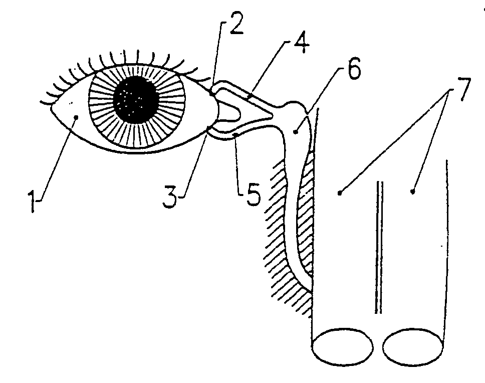
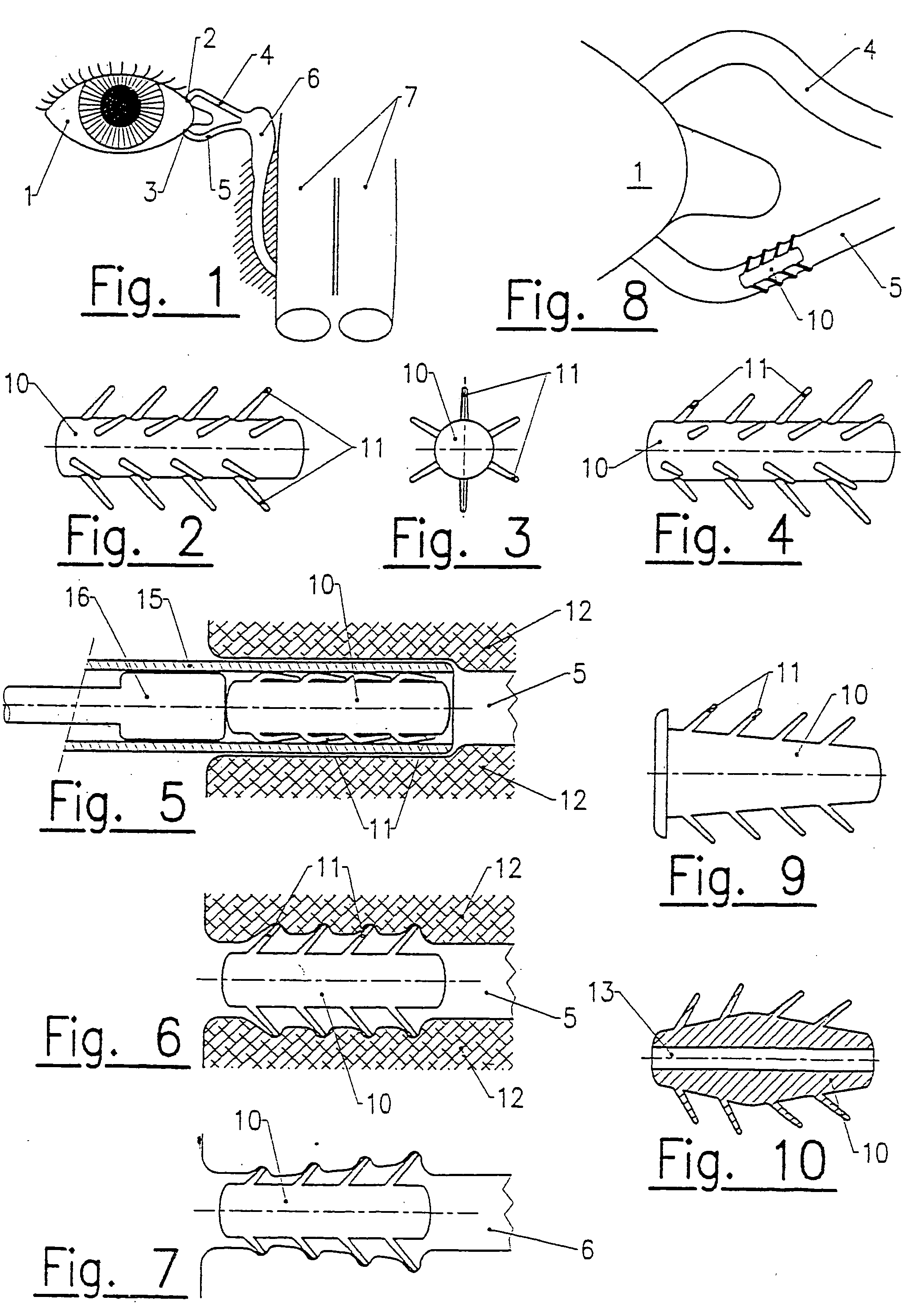
[0020] The device of the present invention shown in FIGS. 2-10, includes a substantially cylindrical body 10, on outer lateral walls of which are implanted flexible elements such as radial pins 11 that can be applied or collapsed against the walls and straightened when released.

[0021] These flexible elements have a sufficient predetermined elasticity to partially penetrate into the inner wall 12 of the canaliculus 4, 5, by straightening up, so as to ensure that the lachrymal plug is firmly held in position as shown in FIG. 5.

[0022] The pins 11 can be arranged in helical formation or any other configuration. Their length can be constant, increasing as shown in FIGS. 4 and 7, decreasing or variable. They are advantageously tilted in the direction of the nasal cavities 7, so that they cannot be displaced by the natural peristalsis of the lachrymal duct which drives tears and foreign bodies inwardly.

[0023] The exact shape of the body 10 can vary. For instance, it can have the form of a ...


PUM


Abstract

The invention concerns lachrymal plugs, and methods for setting said devices. It concerns a lachrymal plug (10) designed to be inserted in the lachrymal canaliculi (5), said plug, optionally provided with an axial duct, comprising on its outer walls flexible elements (11) foldable on said walls to enable the plug to be inserted in the lachrymal duct and adapted to straighten up once the lachrymal plug is set, so as to maintain the latter in position. The invention generally concerns means for controlling the flow of tears running from the surface of the eye towards the nasal cavity.

Description

BACKGROUND OF THE INVENTION[0001] 1. Field of the Invention[0002] The present invention is generally directed to controlling the flow of tears running from the surface of the eye towards the nasal cavity.[0003] 2. Discussion of Background Information[0004] The normal functioning of the human eyeball requires that its outer surface be constantly covered with a lubricating film constituted by tears, that ensure both rinsing and protection due to the natural anti-infectious antibiotics that they contain. They are produced by a series of glands located in the eyelids and about the periphery of the eye.[0005] This method has the drawback of being irreversible, barring a new surgical intervention. To overcome this, removable devices capable of being positioned in a lachrymal duct and removed without surgical intervention have been proposed. For instance, U.S. Pat. No. 5,334,137, filed by "EAGLE VISION," describes a device for controlling the lachrymal fluid that blocks the flow of this fl...

Claims


Application Information

Patent Timeline
IPC IPC(8): A61F9/007
CPCA61F9/00772
Inventor FOUERE, ALAINBIGE, PIERRE
Owner FOUERE ALAIN
Why Eureka
Try Eureka