
Cryogenic cooling apparatus and method such as for magnetic resonance imaging systems

a cryogenic cooling and magnetic resonance imaging technology, applied in the field of apparatus and methods for controlling a cryogenic cooling system, can solve the problems of incompatibility of apparatus and procedures with patient care environments, heavy equipment for storing or otherwise handling cryogenic liquids, and inability to meet the needs of cryogenic liquid storage and other problems, to achieve the effect of improving the patient care environment and reducing the burden

Inactive Publication Date: 2015-07-16
WUHAN ZHONGKE NIUJIN MAGNETIC RESONANCE TECH CO LTD
View PDF6 Cites 10 Cited by
  • Summary
  • Abstract
  • Description
  • Claims
  • Application Information

AI Technical Summary

Benefits of technology

The invention provides a cooling system for a mechanical refrigerator that improves its operational effectiveness during the cooling process. The system includes a thermal link that reduces the effectiveness of the link during the steady state operation of the refrigerator. The link can be a gas gap heat switch or an anti-radiation member that allows liquid to pass through it. The system also includes an adsorbent material that can control the temperature of the gas source, and a mechanical link that is operational at a predetermined temperature range. The thermal links can be positioned in different arrangements and can be used in various types of mechanical refrigerators.

Problems solved by technology

Cryogenic liquids have associated disadvantages in that they are often “consumable” due to leaks within associated apparatus such as “in situ” liquefiers or storage vessels.
Furthermore such apparatus for storing or otherwise handling cryogenic liquids is often bulky and requires special handling procedures.
Such apparatus and procedures are somewhat incompatible with patient care environments.
Despite advances which have been made to date in the technology associated with mechanical refrigerators, the thermodynamic coefficient of performance (COP) and the associated cooling efficiency of such mechanical refrigerators are still rather unsatisfactory.

Method used


Image

  • Cryogenic cooling apparatus and method such as for magnetic resonance imaging systems
  • Cryogenic cooling apparatus and method such as for magnetic resonance imaging systems
  • Cryogenic cooling apparatus and method such as for magnetic resonance imaging systems

Examples


Embodiment Construction

[0089]In order to provide a full understanding of the invention, we firstly describe a known closed cycle refrigerator (CCR) system in accordance with FIG. 10. The system described uses a mechanical refrigerator in the form of a pulse tube refrigerator (PTR). However, as will become clearer from the further description later, the system according to the invention may also be used with other coolers such as a Gifford-McMahon (GM) cooler.

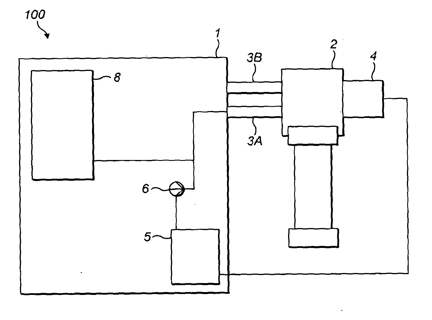
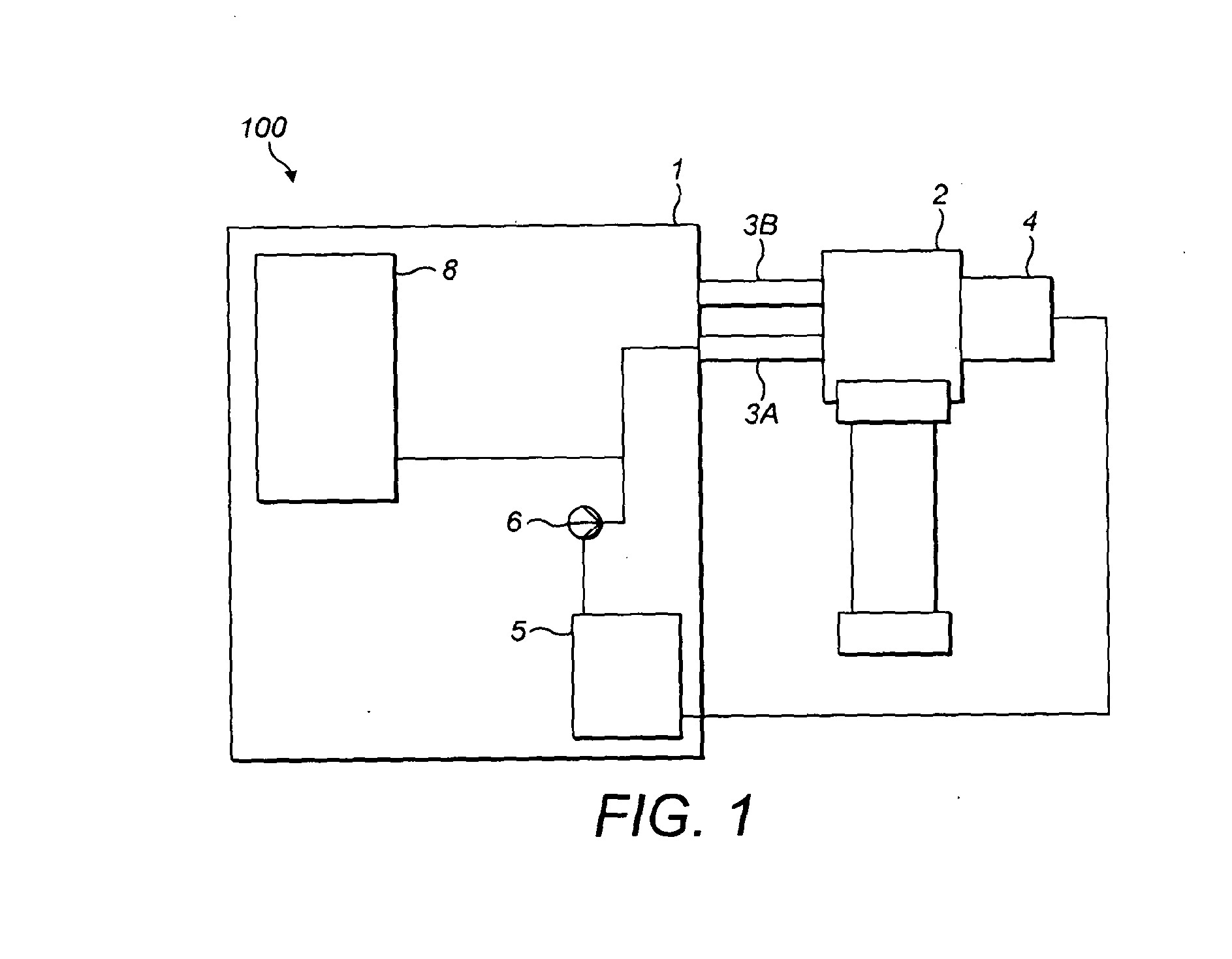
[0090]The system 100′ comprises a scroll compressor 1′ and a pulse tube refrigerator (PTR) 2′. Two gas lines 3A′ and 3B′ connect the scroll compressor 1′ to the pulse tube refrigerator 2′. The gas lines 3A′ and 3B′ are essentially gas pipes which are capable of withstanding a high pressure. The gas line 3A′ is a supply line which contains a coolant gas at a high pressure when in use. The line 3B′ is a return line in the form of a low pressure line. Notably each of the high and low pressures is significantly above atmospheric pressure, for example 23-2...


PUM


Abstract

A cryogenic cooling apparatus comprises a supply gas line and a return gas line adapted to be coupled to a compressor. A coupling element is positioned in gaseous communication with the supply and return gas lines, the coupling element being adapted in use to supply gas to a mechanical refrigerator so that the pressure of said supplied gas is modulated by the coupling element in a cyclical manner. A sensing system is used to monitor the operational state of the mechanical refrigerator and a control system modulates the frequency of the cyclical gas pressure supplied by the coupling element in accordance with the monitored operational state. The mechanical refrigerator has a first cooled stage and a second cooled stage, the second cooled stage being adapted to be coupled thermally with target apparatus to be cooled. A selectively coupleable thermal link is provided for thermally coupling the first cooled stage of the mechanical refrigerator to the second cooled stage in dependence upon the operational state of the mechanical refrigerator. A method of use of the apparatus is also disclosed. The apparatus and method have particular application in a Magnetic Resonance Imaging system.

Description

FIELD OF THE INVENTION[0001]The present invention relates to an apparatus and method for controlling a cryogenic cooling system, particularly one in which certain types of gas compressor are used to drive mechanical refrigerators. The invention finds particular advantage in the cooling system of a Magnetic Resonance Imaging (MRI) system.BACKGROUND TO THE INVENTION[0002]Low temperature properties such as superconductivity and superfluidity are now widely used in a range of different applications including Magnetic Resonance Imaging (MRI), superconducting magnets, sensors and in fundamental research. Historically, the evaporation of cryogenic liquids such as nitrogen or helium has been used as a cooling mechanism in order to reach the low temperatures required for such applications. Cryogenic liquids have associated disadvantages in that they are often “consumable” due to leaks within associated apparatus such as “in situ” liquefiers or storage vessels. Furthermore such apparatus for ...

Claims


Application Information

Patent Timeline
Patent Type & Authority Applications(United States)
IPC IPC(8): A61B5/055F25B49/02F25B9/14
CPCA61B5/055F25B49/022F25B9/145F25B9/14F25D19/006F25B9/10F28D15/0275
Inventor GARSIDE, JOHN
Owner WUHAN ZHONGKE NIUJIN MAGNETIC RESONANCE TECH CO LTD
Learn More