Shipping container having a flame retardant layer and a thermal blocking layer

Active Publication Date: 2017-04-25
NOCHAR
View PDF17 Cites 10 Cited by
  • Summary
  • Abstract
  • Description
  • Claims
  • Application Information

AI Technical Summary

Benefits of technology

[0022]The underlying theory behind these attempts is to extinguish fire, and thereby reduce the effective number of burning batteries before the fires spread to adjacent batteries and/or adjacent containers and batteries, instead of preventing the first or thermal runaways from occurring. Unfortunately, these prior attempts have not been wholly successful in preventing thermal runaway wi

Problems solved by technology

Unfortunately, lithium batteries also have certain disadvantages when compared to other batteries.
For example, lithium batteries can be more expensive to manufacture than alkaline and nickel based batteries.
Another disadvantage of the use of lithium batteries is that they have a greater potential to catch fire than nickel based batteries.
It is believed that the root cause of the propensity of lithium ion batteries to catch fire is a failure or flaw in the separators within the batteries.
When these separators fail to function properly, the battery can fail and catch fire.
These “bad separator” failures can result from poor design, manufacturing flaws, external damage induced on the battery, poor battery pack design, insufficient or inadequate protection being engineered into the design of the battery, and over charging.
The internal short circuit that results from damage to the thin separator results in the subsequent build up of heat.
As such, placing the batteries in an evacuated container, or a sealed container will not prevent the batteries within the container from engaging in a thermal runaway and thereby overheating the container.
This propensity to catch fire can increase the risk to shippers who transport lithium batteries, especially wh

Method used


Image

  • Shipping container having a flame retardant layer and a thermal blocking layer
  • Shipping container having a flame retardant layer and a thermal blocking layer
  • Shipping container having a flame retardant layer and a thermal blocking layer

Examples


Embodiment Construction

[0075]For the purposes of promoting an understanding of the principles of the invention, reference will now be made to the embodiments illustrated in the drawings and specific language will be used to describe the same. It will nevertheless be understood that no limitation of the scope of the invention is thereby intended. Any such alterations and further modifications in the illustrated devices, and such further applications of the principles of the invention as illustrated herein are contemplated as would normally occur to one skilled in the art to which the invention relates.

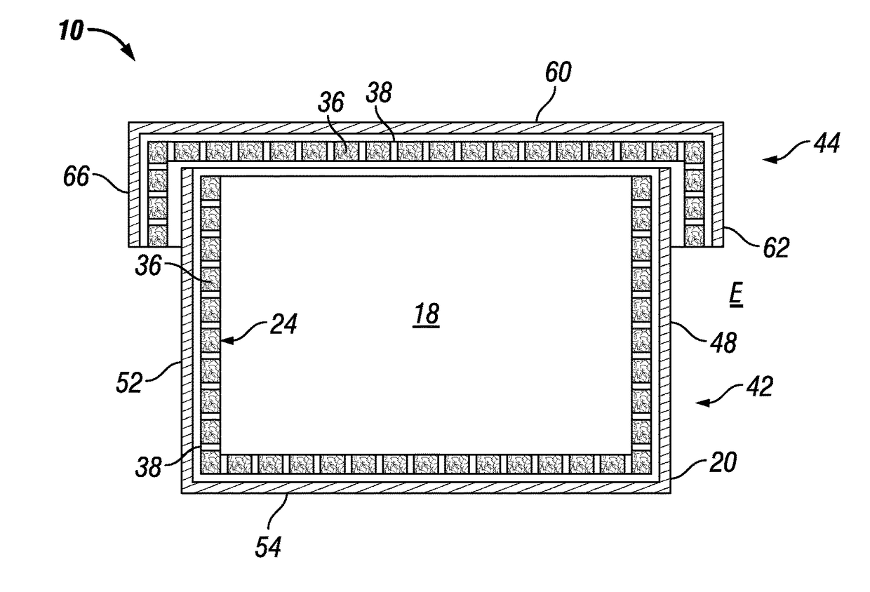
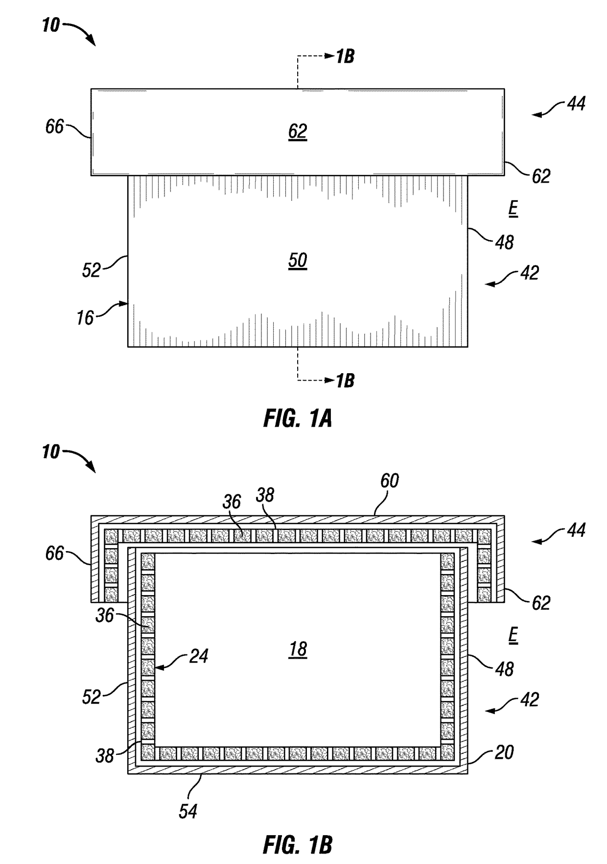
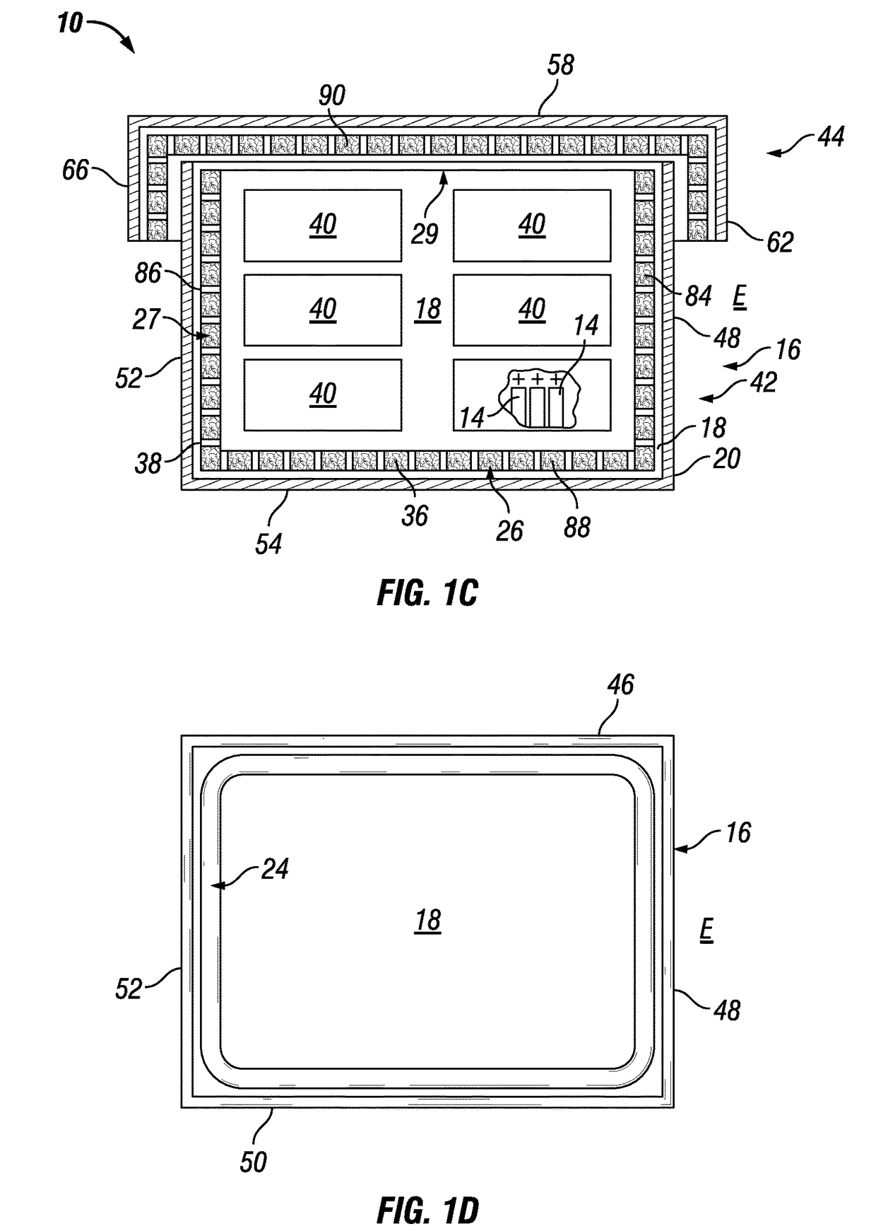
[0076]As best shown in the figures, a shipping container 10 is configured for shipping thermally active materials, such as cases 12 of batteries 14. Although thermal activity can take a wide variety of both heating and cooling functionalities, the primary thermal activity materials for which the shipping container 10 of the present invention is designed, are thermally active materials such as batteries 14, an...


PUM


Abstract

A shipping container for shipping thermally active materials includes a plurality of structural panels that define a container interior, and are configured for receiving the thermally active materials. The container also includes an exterior disposed adjacent to an environment in which the shipping container is disposed. A thermal barrier member is placeable between the thermally active materials and the environment in which the container is placed. The thermal barrier includes a thermal barrier interior panel and a thermal barrier external panel defining a heat absorbing material receiving cavity. A flowable polymer based heat absorbing material is disposed within the heat absorbing material receiving cavity. The thermal barrier is configured to substantially surround the thermally active materials to reduce the passage of thermal energy between the thermally active materials and the environment in which the shipping container is disposed.

Description

PRIORITY CLAIM[0001]The instant application claims benefit of priority to Carl Gehlhausen, and Dennis Campbell U.S. Provisional Patent Application Ser. No. 62 / 042,236 that was filed on 26 Aug. 2014, and which is fully incorporated herein by reference.I. TECHNICAL FIELD OF THE INVENTION[0002]The present invention relates to containers and packaging materials, and more particularly to a container having a thermal barrier member for reducing the transfer of heat from and / or to the container.II. BACKGROUND OF THE INVENTION[0003]With the proliferation of electrically operated portable ‘gadgets,” the number of batteries sold to power these gadgets has mushroomed proportionately. One type of battery whose sales have increased dramatically over the past 10 years is lithium batteries. For example, it is estimated that about 4 million dollars of lithium batteries were sold in 1996, and that about 4 billion dollars in lithium batteries were sold in 2014.[0004]Lithium batteries have advantages ...

Claims


Application Information

Patent Timeline
IPC IPC(8): B65D81/38F17C13/12F17C13/00B65D6/10F17C3/04H01M2/10B65D6/02
CPCF17C3/04B65D7/06B65D7/22B65D81/38B65D81/382F17C13/004F17C13/12H01M2/1094B65D2585/88F17C2201/01Y02E60/10H01M50/24B65D88/74B65D90/06H01M50/30B65D43/22B65D55/02
Inventor GEHLHAUSEN, CARL L.CAMPBELL, DENNIS R.GEHLHAUSEN, DANIEL W.
Owner NOCHAR
Why Eureka
Try Eureka