Annular aerosol jet deposition using an extended nozzle

an aerosol and nozzle technology, applied in the direction of liquid/solution decomposition chemical coating, combustion types, lighting and heating apparatus, etc., can solve the problems of not being able to localize deposition, thin film and thick film deposition of electronic structures are well-developed, and place limitations on microelectronic applications. , to achieve the effect of increasing the working distan

Inactive Publication Date: 2006-01-12
OPTOMEC DESIGN CO
View PDF98 Cites 64 Cited by
  • Summary
  • Abstract
  • Description
  • Claims
  • Application Information

AI Technical Summary

Benefits of technology

[0016] The present invention is an apparatus for depositing a material on a target, the apparatus comprising a device for aerosolizing the material, a deposition flowhead with an input connected to the aerosol source, the flowhead combining the aerosolized material with an annular sheath gas flow, and an extended nozzle attached to the output of the deposition flowhead. An annular gas flow, preferably comprising an outer sheath flow and an aerosol-laden inner flow, is preferably developed within the deposition flowhead and passed through the nozzle. The nozzle preferably increases the working distance so that the target is preferably at least several millimeters from the nozzle. The material is preferably depositable into recessed features of the target.
[0020] Another object of the extended nozzle of the present invention is to provide an interchangeable nozzle, enabling rapid variance of deposited linewidth using the same apparatus.
[0022] A further object of the extended nozzle of the present invention is to provide enhanced deposition characteristics, including but not limited to improved collimation of the jetted aerosol stream, improved focusing and reduced turbulence of the stream, and minimized particle overspray.
[0023] An advantage of the extended nozzle of the present invention is an increased working distance, enabling direct write onto non-planar surfaces, allowing processing and diagnostic equipment to be placed closer to the deposition area, reducing the heat transfer from the platen to the deposition module, and facilitating delivery of material into recessed features.
[0024] Another advantage of the extended nozzle of the present invention is that it is preferably detachable, enabling easy cleaning and clearing of clogs.

Problems solved by technology

Thick film and thin film processes for deposition of electronic structures are well-developed, but have limitations due to high processing temperatures or the need for expensive masks and vacuum chambers.
Thus, the high resistivity of ink jetted conductive polymers places limitations on microelectronic applications.
The process disclosed in U.S. Pat. No. 5,814,152 requires laser melting and ablation of aerosolized material, and is not capable of localized deposition.
The invention of Hochberg does not use a sheath gas to form an annular flow for the purpose of focusing the aerosol stream and preventing accumulation of material at the exit orifice, is limited to the deposition of ink onto paper, and does not disclose a process for aerosolization and deposition of viscous inks or inks composed of particle suspensions.

Method used


Image

  • Annular aerosol jet deposition using an extended nozzle
  • Annular aerosol jet deposition using an extended nozzle
  • Annular aerosol jet deposition using an extended nozzle

Examples


Embodiment Construction

)

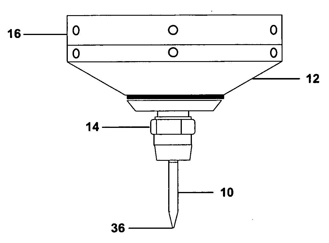
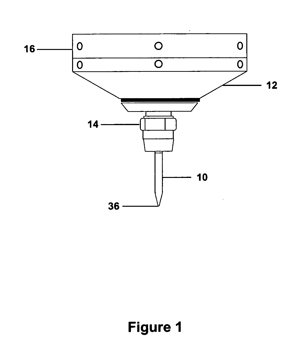
[0032] The present invention relates to maskless, non-contact printing of electronic and biological materials onto planar or non-planar surfaces, and more specifically to apparatuses and methods for high-resolution, maskless deposition of liquid and particle suspensions using aerodynamic focusing. In the most commonly used embodiment, an aerosol stream is focused and deposited onto a planar or non-planar target, forming a pattern that is thermally or photochemically processed to achieve physical and / or electrical properties near that of the corresponding bulk material. The process is termed M3D™, Maskless Mesoscale Material Deposition, and is used to deposit aerosolized materials with linewidths that are an order of magnitude smaller than lines deposited with conventional thick film processes. The process and apparatus are more fully described in U.S. Patent Application Publication No. 2003 / 0228124, incorporated herein by reference. Deposition is performed without the use of masks....


PUM

PropertyMeasurementUnit
lengthaaaaaaaaaa
lengthaaaaaaaaaa
diameteraaaaaaaaaa

Abstract

Method and apparatus for improved maskless deposition of electronic and biological materials using an extended nozzle. The process is capable of direct deposition of features with linewidths varying from a few microns to a fraction of a millimeter, and can be used to deposit features on targets with damage thresholds near 100° C. or less. Deposition and subsequent processing may be performed under ambient conditions and produce linewidths as low as 1 micron, with sub-micron edge definition. The extended nozzle reduces particle overspray and has a large working distance; that is, the orifice to target distance may be several millimeters or more, enabling direct write onto non-planar surfaces. The nozzle allows for deposition of features with linewidths that are approximately as small as one-twentieth the size of the nozzle orifice diameter, and is preferably interchangeable, enabling rapid variance of deposited linewidth.

Description

CROSS-REFERENCE TO RELATED APPLICATIONS [0001] This application is a continuation-in-part application of U.S. patent application Ser. No. 10 / 952,108, entitled “Laser Processing for Heat-Sensitive Mesoscale Deposition”, filed on Sep. 27, 2004, which claims the benefit of the filing of U.S. Provisional Patent Application Ser. No. 60 / 506,495, entitled “Laser Treatment Process for Low-Temperature Deposition”, filed on Sep. 26, 2003 and U.S. Provisional Patent Application Ser. No. 60 / 508,759, entitled “Method for Fabricating Resistive Structures”, filed on Oct. 3, 2003, and which is also a continuation-in-part application of U.S. patent application Ser. No. 10 / 746,646, entitled “Apparatuses, Methods, and Precision Spray Processes for Direct Write and Maskless Mesoscale Material Deposition”, filed on Dec. 23, 2003, which is both a continuation-in-part application of U.S. patent application Ser. No. 09 / 844,666, entitled “Precision Spray Processes for Direct Write Electronic Components”, fi...

Claims


Application Information

Patent Timeline
Patent Type & Authority Applications(United States)
IPC IPC(8): B05C5/00B05B1/30B05D1/02
CPCH05K3/125
Inventor KING, BRUCE H.RENN, MICHAEL J.ESSIEN, MARCELINOMARQUEZ, GREGORY J.GIRIDHARAN, MANAMPATHY G.SHEU, JYH-CHERNG
Owner OPTOMEC DESIGN CO
Why Eureka
Try Eureka