Multiple parallel confocal system and surface measurement method using the same

a confocal system and confocal technology, applied in the field of multiple parallel confocal systems and surface measurement methods, can solve the problems of reducing the efficiency of quality inspection, requiring a substantially long period of time for measuring the large area, and difficult to measure a large area with a high resolution limit, so as to reduce the formation of contamination and scratches

Active Publication Date: 2015-03-26
IND ACADEMIC CORP FOUND YONSEI UNIV
View PDF7 Cites 19 Cited by
  • Summary
  • Abstract
  • Description
  • Claims
  • Application Information

AI Technical Summary

Benefits of technology

[0030]As described above, the multiple parallel confocal microscope system allows the working distance between the microlenses and the measuring object to be extended to reduce the formation of the contamination and scratches on the surfaces of the microlenses and the measuring object, and further, the optical pinhole effect can be obtained using the optical paths of the relay lens unit, without any having a physical pinhole.
[0031]Furthermore, under the microlens array structure wherein the microlenses in one column are located between the distance between the microlenses in another column, the multiple optical probe or the measuring object is moved continuously in the longitudinal direction (single direction) thereof, so that the measuring object can be scanned over the rectangular area or linear area thereof corresponding to the traverse width of the microlenses constituting the columns.
[0032]In scanning the unit area of the multiple optical probe, additionally, unlike the conventional practice wherein the beam spots are moved longitudinally and traversely over the two-dimensional area designated in the unit of beam spot, the present invention can scan the unit area of the multiple optical probe rapidly by the continuous movement of the multiple optical probe in the single direction.
[0033]In scanning the large area exceeding the unit area of the multiple optical probe, further, unlike the existing optical system wherein the movements of the beam spots for filling the surface and the movements and stop of the beam spots to the unit position of the multiple optical probe are repeatedly conducted one by one, the present invention can scan the unit area of the multiple optical probe rapidly by the continuous movement of the multiple optical probe in the single direction.

Problems solved by technology

As the size of the measuring object becomes large, recently, it is hard to measure a large area with a high resolution limit, and according to the conventional optical system having the multiple optical probes, the movements of the beam spots for filling the surface of the sample and the movements and stop of the beam spots to the unit positions of the multiple optical probes are repeatedly conducted one by one to achieve the measurement of the surface of the sample, thus needing a substantially long period of time for measuring the large area and lowering the efficiency of quality inspection.

Method used


Image

  • Multiple parallel confocal system and surface measurement method using the same
  • Multiple parallel confocal system and surface measurement method using the same
  • Multiple parallel confocal system and surface measurement method using the same

Examples


first embodiment

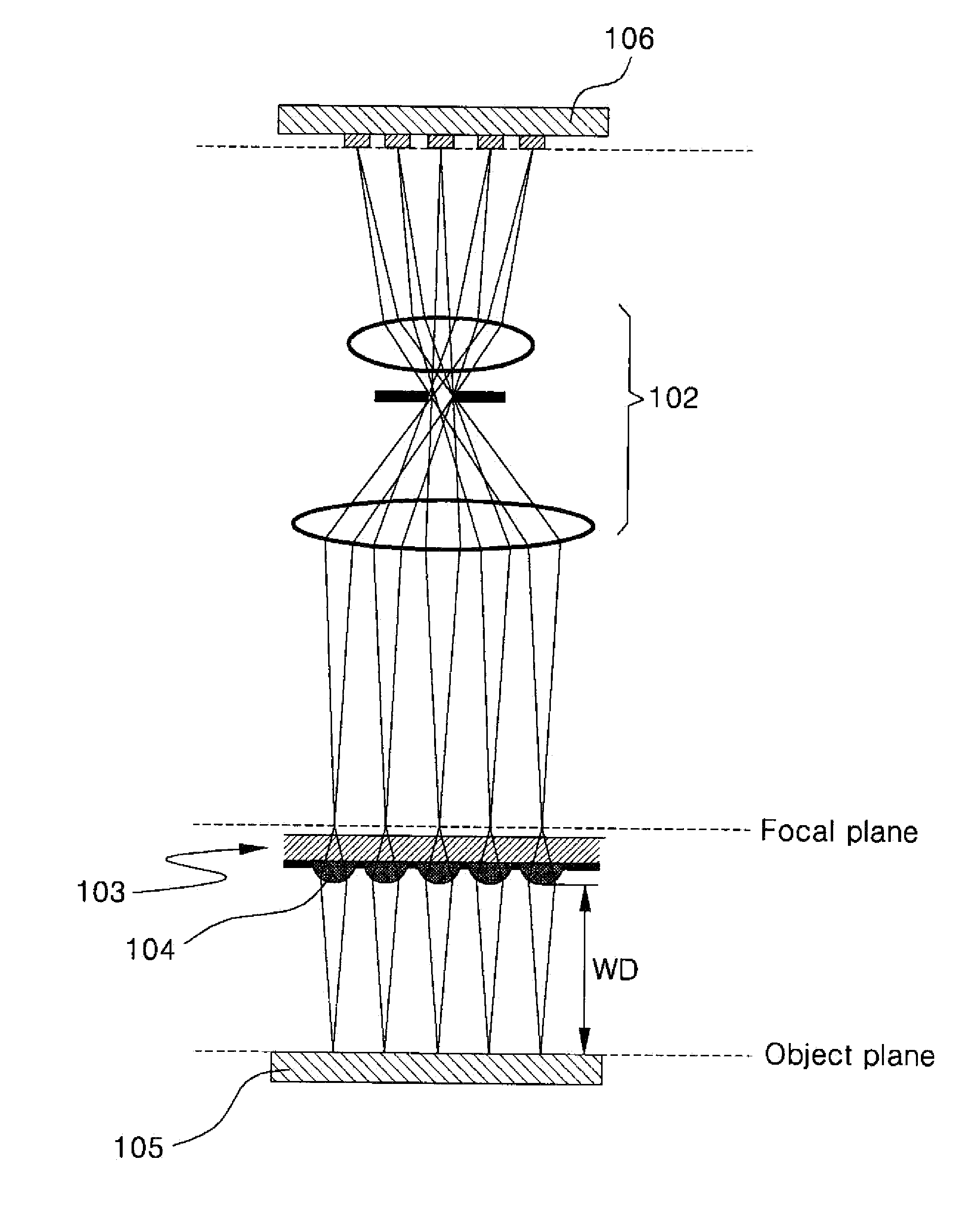
[0059]FIG. 7 is a concept view showing the configuration of a multiple parallel confocal system according to the present invention.

[0060]As shown in FIG. 7, a multiple parallel confocal system according to a first embodiment of the present invention includes: a light source (not shown) for irradiating light; a relay lens unit 102 through which the light traveling toward a measuring object 105 or the light reflected from the measuring object 105 is passed, the relay lens unit 102 having one or more lens for focusing the light irradiated from the light source; a multiple optical probe 103 having a microlens array on which a plurality of microlenses 104 is arranged, the microlenses 104 into which the focused light through the relay lens unit 102 is incident; and a photo detector 106 for detecting the incident light reflected from the measuring object 105 and passed through the microlenses 104 and the relay lens unit 102.

[0061]The relay lens unit 102 is an optical microscope for focusin...

second embodiment

[0070]FIG. 9 shows a multiple parallel confocal system according to the present invention, wherein the relay lens unit has a telecentric lens and a beam splitter.

[0071]As shown in FIG. 9, the relay lens unit 102 as the optical microscope for focusing the light includes: a telecentric lens 108 having two focusing lenses 108a and 108c and an aperture 108b disposed between the focusing lenses 108a and 108c; and a beam splitter 107 disposed under the optical axis of the telecentric lens 108 so as to convert the advancing paths of light irradiated from the light source.

[0072]At this time, as shown in FIG. 9, the light source is disposed under the optical axis of the telecentric lens 108, and alternatively, it is disposed above the optical axis of the telecentric lens 108. In this case, if the light source is disposed above the optical axis of the telecentric lens 108, the beam splitter 107 is disposed above the telecentric lens 108.

third embodiment

[0073]On the other hand, FIG. 10 shows a multiple parallel confocal system according to the present invention, wherein an aperture 140 having pin holes 142 formed thereon is additionally disposed on a focal plane where the focuses of the relay lens unit 102 and the back focuses of the microlenses 104 meet.

[0074]FIG. 11 is a concept view showing the checking state of the surface of the measuring object using the confocal system according to the present invention. As shown in FIG. 11, if the measuring object 105 is measured by using the confocal system according to the present invention which has the working distance WD longer than the existing focal length f of the microlens, the surface of the measuring object 105 can be scanned without any contact with the microlenses 104, thus preventing the surfaces of the microlenses 104 and the measuring object 105 from being contaminated or scratched due to the contact therebetween. Furthermore, the existing confocal system needs a separate de...


PUM

PropertyMeasurementUnit
focal distanceaaaaaaaaaa
optical axisaaaaaaaaaa
distanceaaaaaaaaaa

Abstract

The present invention relates to a multiple parallel confocal system including: a light source for irradiating light; a relay lens unit through which the light traveling toward a measuring object or the light reflected from the measuring object is passed, the relay lens unit having one or more lens for focusing the light irradiated from the light source; a multiple optical probe having a microlens array on which a plurality of microlenses is arranged, the microlenses into which the focused light through the relay lens unit is incident; and a photo detector for detecting the incident light reflected from the measuring object and passed through the microlenses and the relay lens unit.

Description

TECHNICAL FIELD[0001]The present invention relates to a multiple parallel confocal system and a surface measurement method using the same.BACKGROUND ART[0002]Recently, a confocal microscope is a device used to irradiate given wavelength of light to a sample, to pass the reflected light to a confocal aperture like a pinhole, and to detect only the light emitted from the focus of an objective lens through a photo detector.[0003]FIG. 1 is a concept view showing a confocal optical system to which the principle of a general confocal microscope is applied.[0004]Referring to FIG. 1, the confocal microscope includes: a light source 11 for irradiating laser light; a beam splitter 13 for converting the advancing path of the incident light thereinto; an objective lens 15 for focusing the light irradiated from the light source 11 thereto; and a photo detector 19. Further, the confocal microscope includes an aperture 17 disposed between the beam splitter 13 and the photo detector 19 so as to all...

Claims


Application Information

Patent Timeline
Patent Type & Authority Applications(United States)
IPC IPC(8): G02B21/06G01N21/55G02B3/00G01B11/24
CPCG02B21/06G01B11/24G01N2201/06113G02B3/0006G01N21/55G02B3/0056G02B21/004G02B21/0032G01N21/00G01N21/15
Inventor KANG, SHINILL
Owner IND ACADEMIC CORP FOUND YONSEI UNIV
Why Eureka
Try Eureka