[0008] Examples of such prior art CCD-based hand-held bar code symbol readers are disclosed in U.S. Pat. Nos. Re. 36,528, 5,777,314, 5,756,981, 5,627,358, 5,484,994, 5,786,582, and 6,123,261 to Roustaei, each assigned to Symbol Technologies, Inc. and incorporated herein by reference in its entirety. In such prior art CCD-based hand-held scanners, an array of LEDs are mounted in a scanning head in front of a CCD
image sensor that is provided with a
cylindrical lens assembly. The LEDs are arranged at an
angular orientation relative to a central axis passing through the scanning head so that a fan of light is emitted through the
light transmission aperture thereof that expands with increasing distance away from the LEDs. The intended purpose of this
LED illumination arrangement is to increase the "
angular distance" and "
depth of field" of such hand-held image-based bar code symbol readers. However, even with such improvements in LED illumination techniques, the working distance of such hand-held scanners can only be extended by using more LEDs within the scanning head of such scanners to produce greater illumination output therefrom, thereby increasing the cost, size and weight of such scanning devices.
[0009] Other CCD-based hand-held bar code symbol readers employing LED illumination have been proposed. For example, U.S. Pat. No. 5,192,856 to Schaham discloses a hand-held image
scanner which uses a LED and beam forming optics (which include collimating and cylindrical lenses) to produce a beam of LED-based illumination for illuminating a bar code symbol on an object, and cylindrical optics mounted in front a linear CCD
image detector for projecting a narrow a
field of view about the illumination, thereby enabling collection and focusing of light reflected off the bar code symbol onto the linear CCD
image detector.
[0010] CCD-based hand-held bar code symbol readers employing CCD image
laser illumination have been proposed. For example, U.S. Pat. No. 4,963,756 to Quan et al discloses a hand-held image
scanner using a
laser source and Scheimpflug optics for focusing a planar
laser illumination beam reflected off a bar code symbol onto a 2-D CCD image
detector. U.S. Pat. No. 5,621,203 to Swartz et al discloses the use of a
cylindrical lens to generate from a single
laser diode an elongated beam of
laser light. The fixed, static elongated beam is redirected by an oscillating mirror or lens such that it fans out an angle sufficient to illuminate a code pattern at a working distance and is swept in a direction transverse to the elongated dimension of the beam. A lens is mounted before a linear CCD image array, to receive diffused reflected
laser light from the bar code symbol surface. And U.S. Pat. No. 5,988,506 to Schaham et al, herein incorporated by reference, discloses the use of a
cylindrical lens to generate from a single
visible laser diode (VLD) a narrow focused line of
laser light which fans out an angle sufficient to fully illuminate a code pattern at a working distance. As disclosed, mirrors can be used to fold the
laser illumination beam towards the code pattern to be illuminated in the
working range of the system. Also, a horizontal linear
lens array consisting of lenses is mounted before a linear,CCD image array, to receive diffused reflected laser light from the code symbol surface. Each
single lens in the linear
lens array forms its own image of the
code line illuminated by the laser illumination beam. Also, subaperture diaphragms are required in the CCD array plane to (i) differentiate image fields, (ii) prevent diffused reflected laser light from passing through a lens and striking the image fields of neighboring lenses, and (iii) generate partially-overlapping fields of view from each of the neighboring elements in the
lens array.
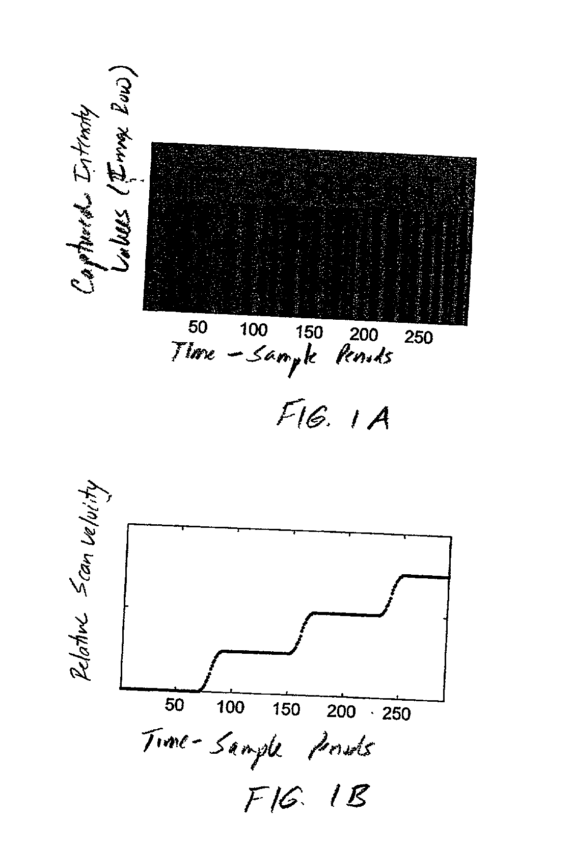
[0021] Thus, there is a great need in the art for improved image-based techniques / devices that provide
velocity estimation / aspect ratio compensation and image-based jitter
estimation and compensation to compensate for aspect ratio distortions and jitter distortions, which are suitable for use in a hand-held bar code symbol reader in order to provide cost-effective distortion-free real-time
image acquisition and image-based bar code symbol reading suitable for many diverse applications, such as reading dense 2-D bar code symbols.

