

Method of forming a sputtering target assembly and assembly made therefrom
a technology of sputtering target and assembly, which is applied in the direction of manufacturing tools, forging/pressing/hammering equipment, soldering equipment, etc., can solve the problems of affecting the performance of the sputtering target assembly, generating very high mechanical stress in the metal body, and causing bond failur
- Summary
- Abstract
- Description
- Claims
- Application Information
AI Technical Summary
Benefits of technology
Problems solved by technology
Method used
Image

Examples
Embodiment Construction
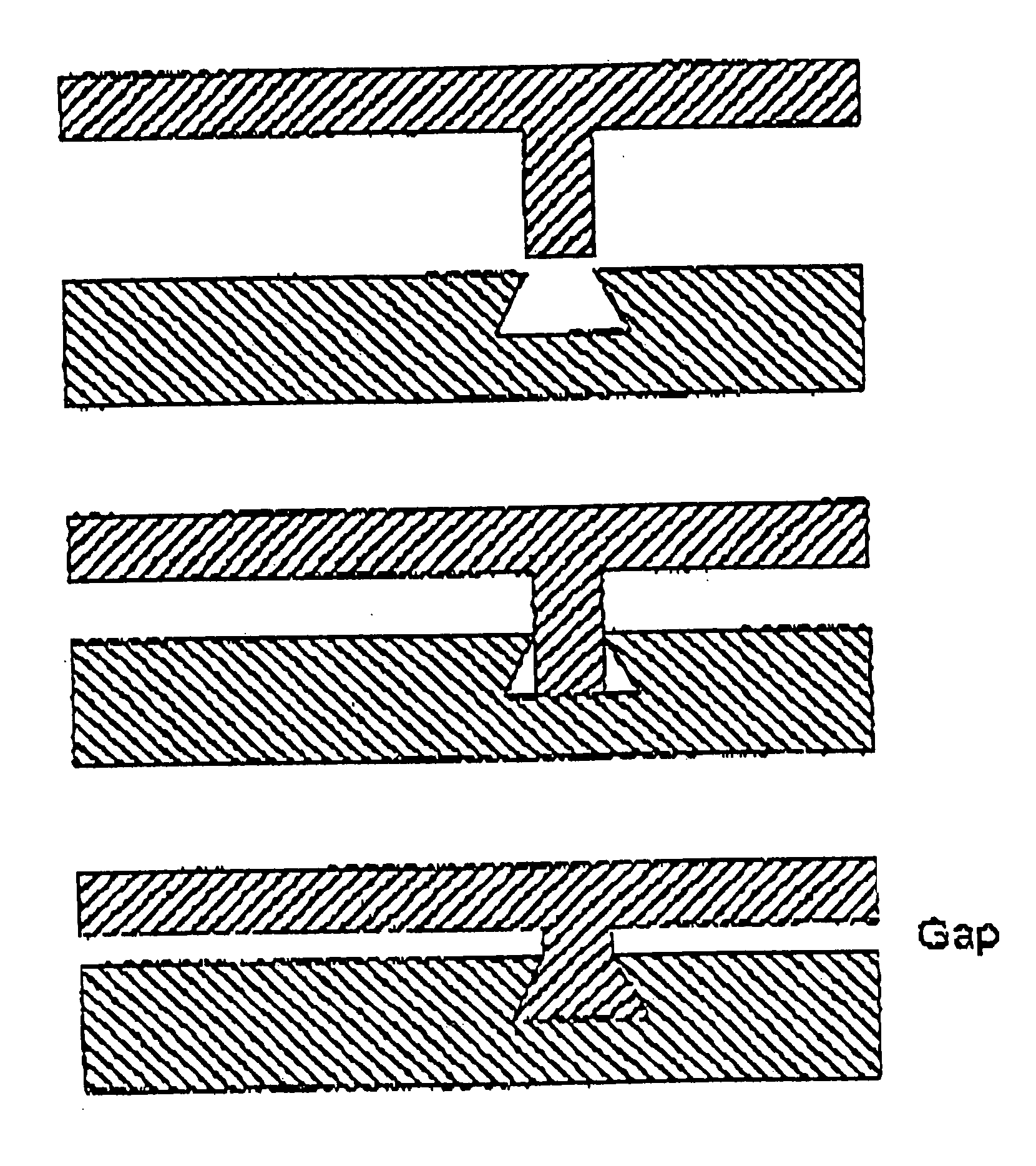
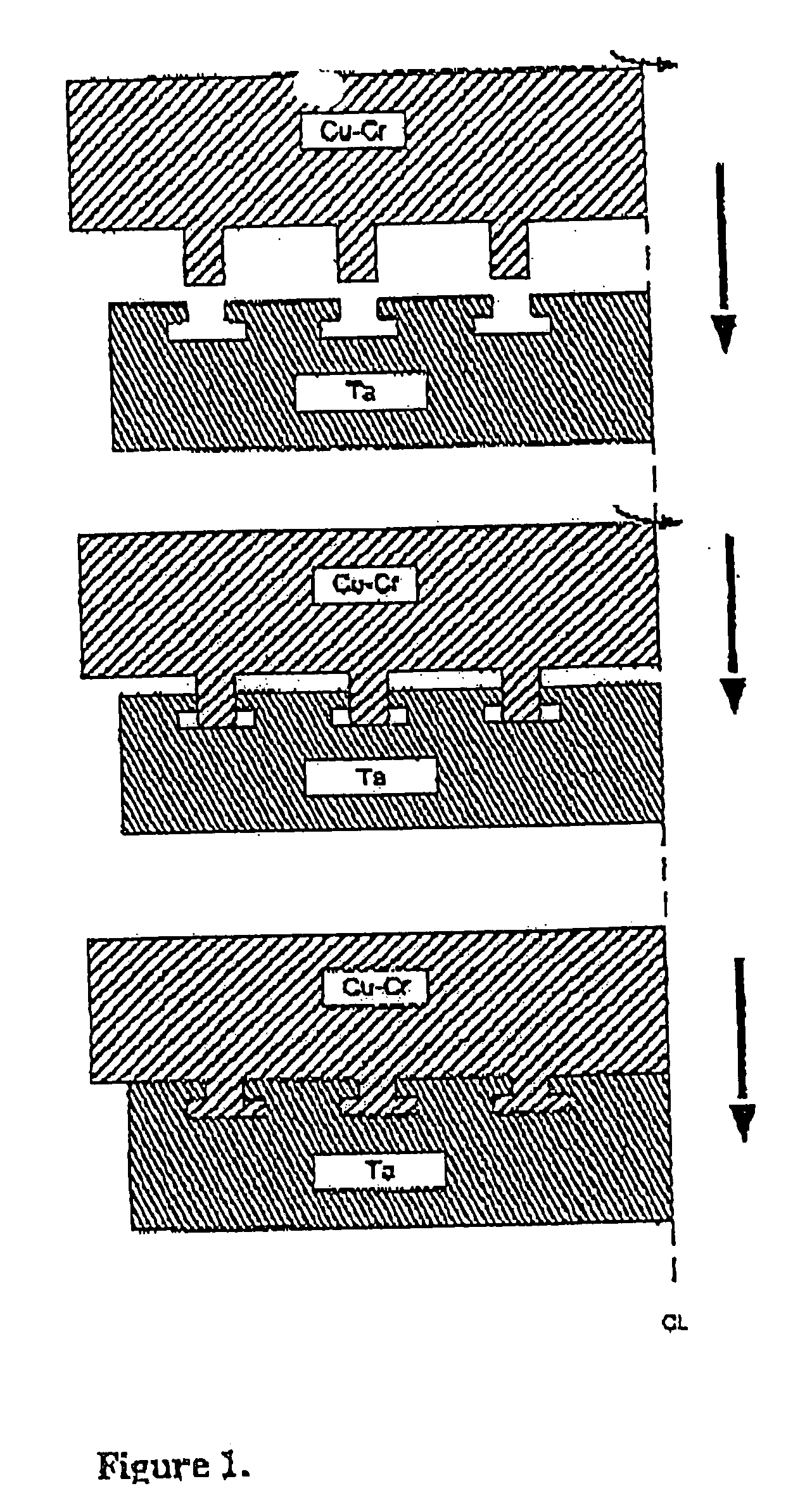
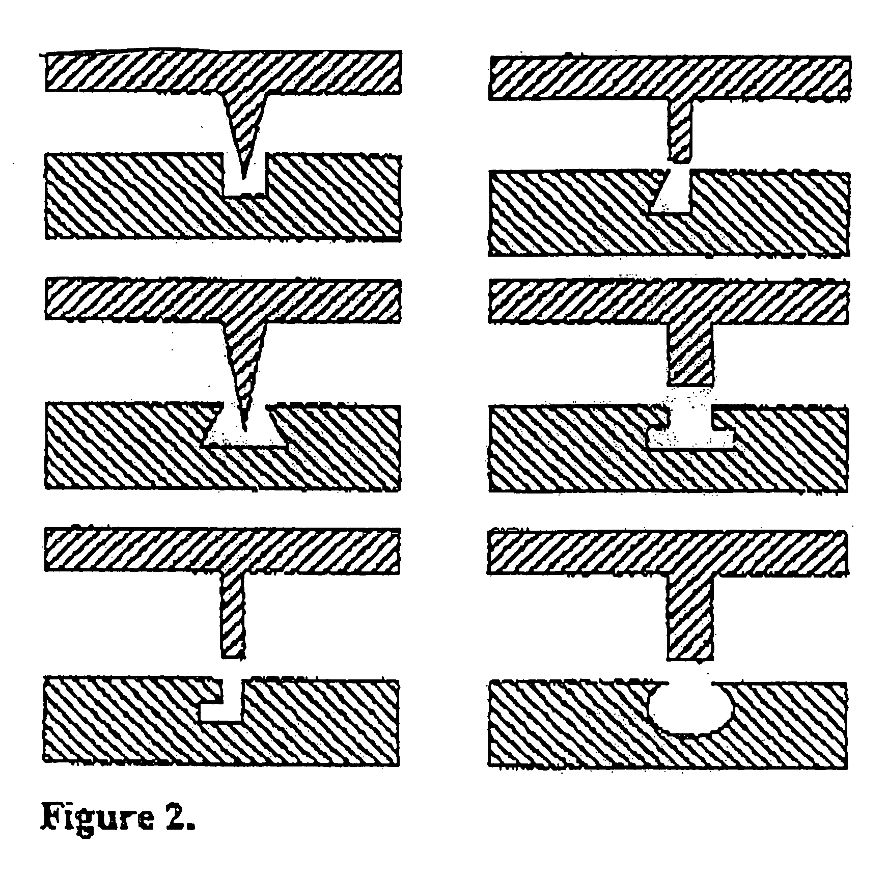
[0021] The present invention is directed to a method of assembling a sputtering target assembly by a bonding process that includes fixing a target member to a backing member, preferably at a low temperature. The method includes positioning an assembly member having a bonding side with a plurality of projections, and an assembly member having a bonding side with a plurality of grooves adapted to receive the projections, such that the projections and said grooves are in substantial registration; slidably contacting a portion of at least one projection with a portion of at least one groove; and partially deforming said at least one projection(s) to at least partially fill the groove(s), thereby bonding the target member and the backing member when the projection(s) hardens.
[0022] Preferably, the sputtering target assembly, as described above, contains two assembly members, i.e., a backing plate member and a sputtering target member. The sputtering target member and the backing plate ca...
PUM
| Property | Measurement | Unit |
|---|---|---|
| Force | aaaaa | aaaaa |
| Pressure | aaaaa | aaaaa |
| Pressure | aaaaa | aaaaa |
Abstract
Description
Claims
Application Information