Display panel module

a technology of display panel and module, which is applied in the direction of identification means, instruments, optical elements, etc., can solve the problems of inability to shield electromagnetic interference, increase the thickness and weight of the pdp set, increase the cost of manufacture, etc., and achieve the effect of effective shielding, preventing contrast deterioration (tonal fading), and preventing the formation of black layer

Inactive Publication Date: 2005-01-27
LG ELECTRONICS INC
View PDF11 Cites 35 Cited by
  • Summary
  • Abstract
  • Description
  • Claims
  • Application Information

AI Technical Summary

Benefits of technology

[0035] The display panel module of the present invention uses the conductive tape for earthing the EMI shielding film by adhering the conductive tape from inside to outside the front filter. Therefore, the electromagnetic waves and / or near infrared rays of the PDP with the film type front filter can be more effectively shielded.
[0036] Moreover, since the black material included in the EMT shielding film is formed on the side where the user can see, contrast deterioration (tonal fading) can be prevented. Also, since the conductive metal patterning and the black material patterning are carried out at the same time, the black layer forming process can be eliminated and as a result of this, the manufacture process is much simplified and the cost of manufacture is reduced.

Problems solved by technology

However, because the glass type front filter 40 includes a glass substrate made from the reinforced glass, which is relatively thick, the thickness and weight of the PDP set were increased, and the cost of manufacture was also increased.
As a result of this, the film type front filter 90 is not capable of shielding the electromagnetic interference.

Method used


Image

  • Display panel module
  • Display panel module
  • Display panel module

Examples


Embodiment Construction

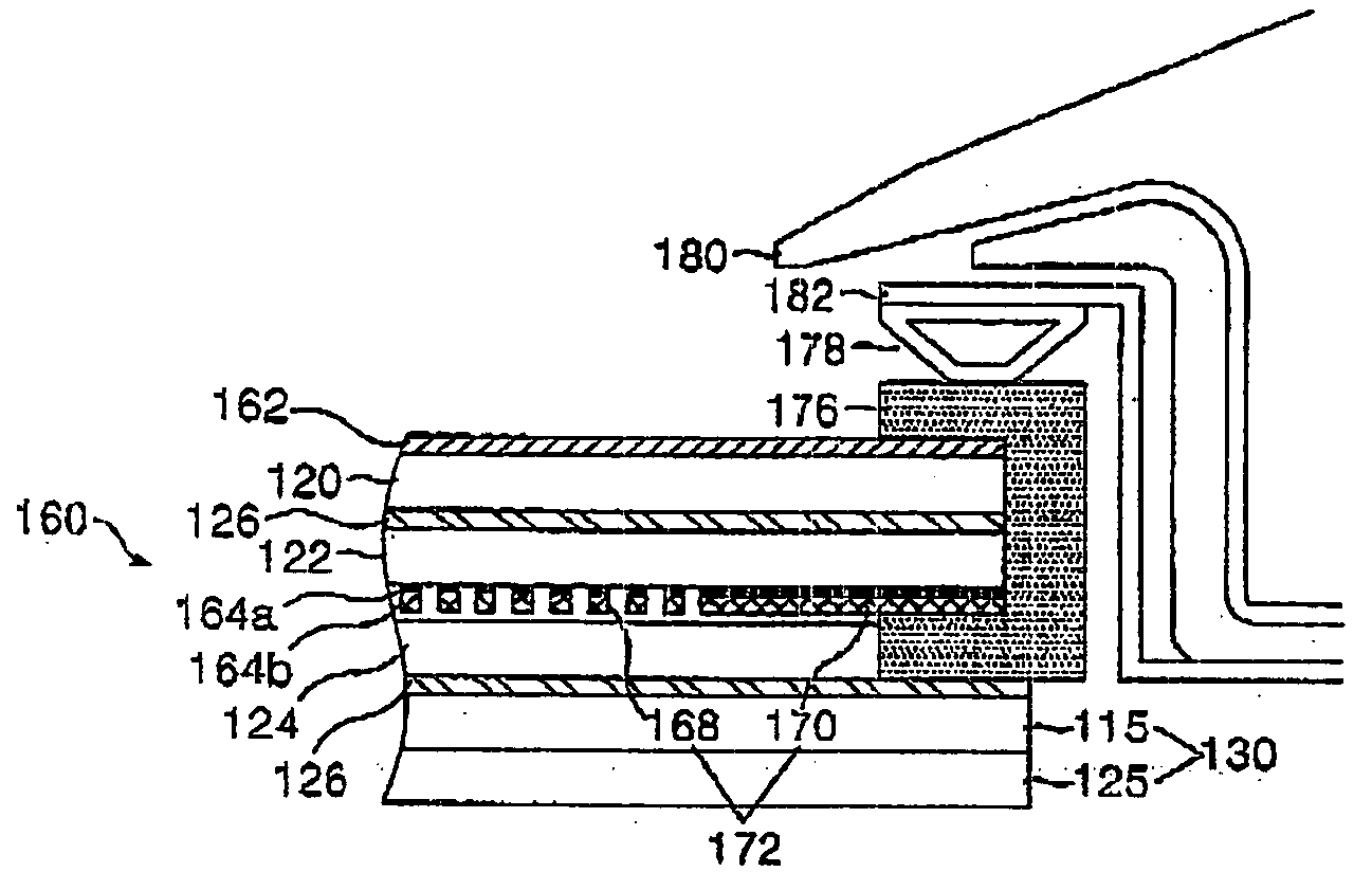
[0047] The following detailed description will present a preferred embodiment of the invention in reference to the accompanying drawings FIGS. 7 and 8. FIG. 7 is a cross-sectional view a film type front filter of the present invention.

[0048] As shown in FIG. 7, the film type front filter 160 includes an EMI shielding film 172 and an antireflection coating 162, which are formed sequentially on an upper plate 115 of a PDP 130.

[0049] The antireflection coating 162 is formed on the front surface of a first base film 120 and prevents incident light rays from outside from reflecting back to the outside.

[0050] The EMI shielding film 172 absorbs electromagnetic waves generated from the PDP 130 and shields the emission of the electromagnetic waves to outside. The EMI shielding film 172 is formed on the rear surface of the first base film 120 and its front surface is adhered to the rear surface of a second base film 122 through an adhesive 126. The EMI shielding film 172 includes a conduci...


PUM

PropertyMeasurementUnit
thicknessaaaaaaaaaa
wavelength bandaaaaaaaaaa
conductiveaaaaaaaaaa

Abstract

Disclosed is a display panel module including: a display panel; a film type front filter formed on the display panel for being combined with the display panel; and a ground electrode coupled to an EMI shielding film of the film type front filter and upwardly bent to encompass at least one side of the film type front filter, and thereby preventing the emission of electromagnetic waves to outside.

Description

BACKGROUND OF THE INVENTION [0001] 1. Field of the Invention [0002] The present invention relates in general to a display panel module, more particularly, to a display panel module having a front filter capable of shielding EMI. [0003] 2. Discussion of the Background Art [0004] In general, PDPs display an image by controlling gas discharge time of each pixel on the basis of digital video data. Typical examples of these PDPs are AC FDPs, as shown in FIG. 1. The AC PDP includes three electrodes and is driven by an AC voltage. [0005]FIG. 1 is a perspective view of a related art AC PDP 30. More particularly, FIG. 1 illustrates the structure of a discharge cell corresponding to a sub-pixel. [0006] As shown in FIG. 1, the discharge cell is divided into an upper plate 15 and a lower plate 25. The upper plate 15 includes an upper substrate 10 where a sustain electrode pair 12A and 12B, an upper dielectric layer 14, and a protective film 16 are formed in sequence. The lower plate 25 includes...

Claims


Application Information

Patent Timeline
Patent Type & Authority Applications(United States)
IPC IPC(8): G02B1/10G02B1/11G09F9/00H01J11/12H01J11/44H01J17/49H01K1/26H01K1/30H05K9/00
CPCG02F2001/133331H01J2211/446H01J11/44H01J11/12G02F1/133331
Inventor KIM, KYUNG KUCHA, HONG-RAECHANG, MYEONG SOO
Owner LG ELECTRONICS INC
Why Eureka
Try Eureka