Implantable medical lead and system, and method of use thereof

a medical lead and implantable technology, applied in the field of medical leads, can solve the problems of increasing length, adding complexity and cost, and being difficult to push, and achieving the effect of significantly longer leads having a stiffening member within and being somewhat unwieldy

a medical lead and implantable technology, applied in the field of medical leads, can solve the problems of increasing length, adding complexity and cost, and being difficult to push, and achieving the effect of significantly longer leads having a stiffening member within and being somewhat unwieldy

US20050021119A1Inactive Publication Date: 2005-01-27MEDTRONIC INC

Image

  • Implantable medical lead and system, and method of use thereof
  • Implantable medical lead and system, and method of use thereof
  • Implantable medical lead and system, and method of use thereof

Examples


Embodiment Construction

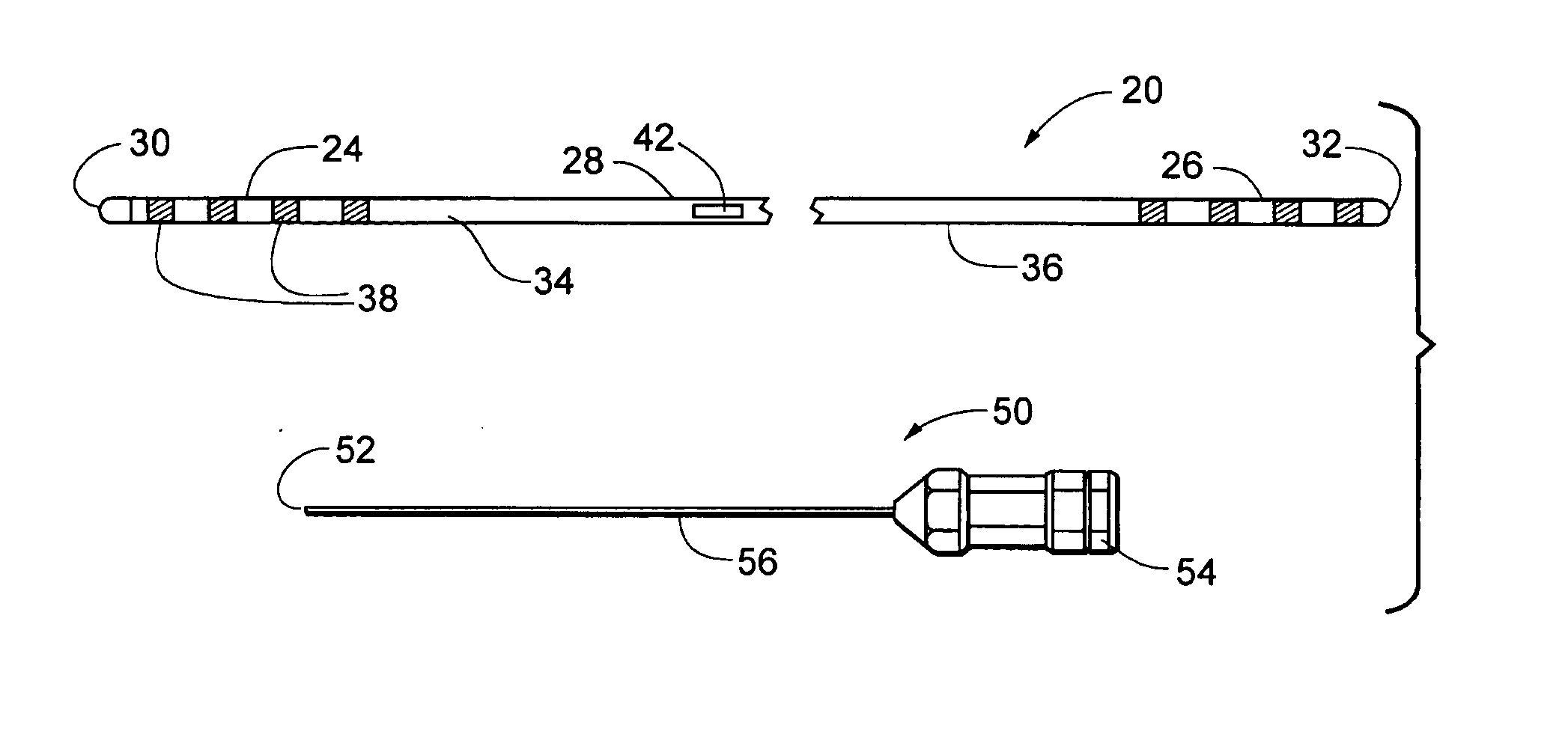
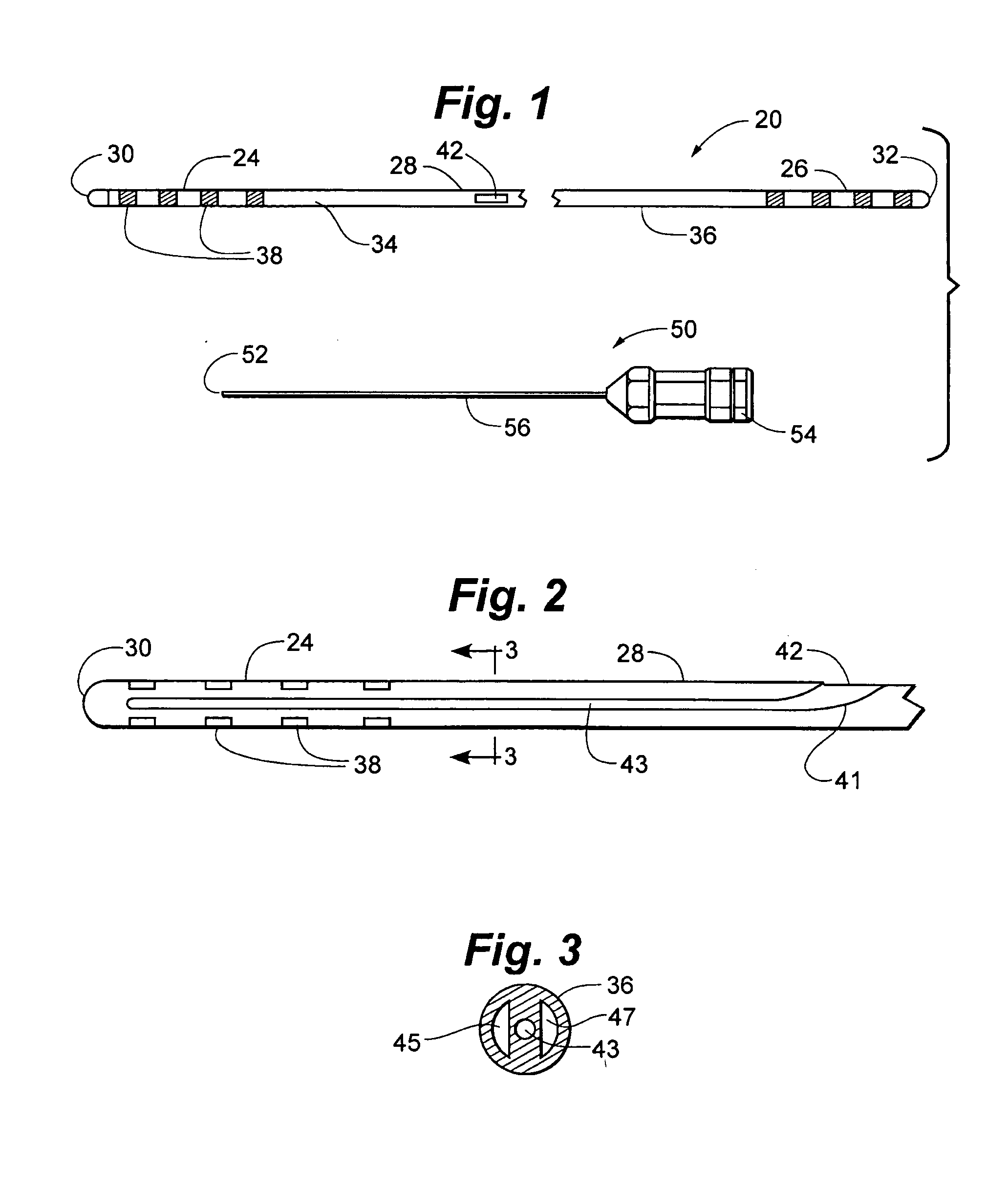
[0039]FIG. 1 illustrates a neurological stimulation lead 20 having a distal region 24, a proximal region 26, and an immediate region 28 disposed between the distal and proximal regions. In a preferred embodiment, the intermediate region is defined to lie between the innermost distal and proximal electrical contacts described below. A stylet entrance or insertion part 42 may be seen in intermediate region 28. Lead 20 can be formed of a body or shaft 34 extending between a distal end 30 and a proximal end 32. Lead body 34 has an exterior surface or tubular side wall 36. Lead body 34 is preferably formed of a polymeric material, for example, polyurethane or silicone.

[0040] Lead distal region 24 may include a number of electrodes 38, which may, for example, be disposed concentrically about lead body 34 in a spaced-apart configuration. Electrodes 38 may also be described as electrical contacts or contacts. Electrodes 38 are normally adapted to be inserted into the human body, are extern...


PUM


Abstract

Implantable medical leads, lead assemblies, and methods for implanting the leads into the human body, for example, for use within the epidural spaces of the spinal column to manage pain. A stylet lumen extends within the lead between a side-wall stylet entrance port and a lead distal region. In use, exemplary stylets may be inserted through the lead stylet port to stiffen only the distal portion of the lead, and the distal portion of the lead inserted through an introducer needle into the human body. The stiffened distal portion of the lead may be short and easily controllable.

Description

RELATED APPLICATIONS [0001] This application is a continuation-in-part of U.S. patent application Ser. No. 10 / 423,179, filed Apr. 25, 2003, which is incorporated herein by reference in its entirety.FIELD OF THE INVENTION [0002] This application relates generally to medical leads, and more specifically to implantable, electrical neurological leads. BACKGROUND OF THE INVENTION [0003] Implantable leads having externally exposed ring or band electrodes can be used to deliver electrical stimulation to surrounding tissue and / or to sense electrical energy produced by the surrounding tissue. Such leads are often implanted, for example, within the epidural or intrathecal spaces of the spinal column, along peripheral nerves, within the brain, and about the heart. Electrical stimulation of the spinal cord has been shown to be effective in relieving intractable pain in some patients. Such electrical stimulation can reduce or eliminate the use of pain relieving drugs. [0004] One such lead is for...

Claims


Application Information

Patent Timeline
27 Jan 2005
Publication
US20050021119A1
IPC
A61N1/05
CPC
A61N1/0529; A61N1/0558; A61N1/0551
Inventors
SAGE, SHAHN S.; HERNANDEZ, JOSE M.