Fiber reinforced composite liner for lining an existing conduit and method of manufacture

a fiber reinforced composite liner and conduit technology, applied in the direction of shaft equipment, surface layering apparatus, manufacturing tools, etc., can solve the problems of near the pipe joint, and the deterioration of the pipe itsel

Inactive Publication Date: 2005-02-10
INA ACQUISITION
View PDF32 Cites 26 Cited by
  • Summary
  • Abstract
  • Description
  • Claims
  • Application Information

AI Technical Summary

Benefits of technology

[0012] Generally speaking, in accordance with the invention, a reinforced composite tubular liner for cured in place pipe rehabilitation of an existing pipeline having a plurality of high-strength low-elongation fiber bundles disposed circumferentially at the inner and outer surfaces of the liner is provided. The bundles of reinforcing fibers are continuous lengths of reinforcing fibers laid out in tubular form adjacent to and parallel to each other on the inner and outer surfaces of at least one resin absorbent tubular layer therebetween. The inner reinforcing layer is bundles of reinforcing fibers that may be attached to a thin porous scrim fo

Problems solved by technology

It is generally well known that conduits or pipelines, particularly underground pipes, such as sanitary sewer pipes, storm sewer pipes, water lines and gas lines that are employed for conducting fluids frequently require repair due to fluid leakage.
The leakage may be due to improper installation of the original pipe, or deterioration of the pipe itself due to normal aging or to the effects of conveying corrosive or abrasive material.
Cracks at or near pipe joints may be due to environmental conditions such as earthquakes or the movement of large vehicles on the overhead surface or similar natural or man made vibrations, or other such causes.
Regardless of the cause, such leakages are undesirable and may result in waste of the fluid being conveyed within the pipeline, or result in damage to the surrounding environment and possible creation of a dangerous public health hazard.
If the leakage continues it can lead to structural failure of the

Method used


Image

  • Fiber reinforced composite liner for lining an existing conduit and method of manufacture
  • Fiber reinforced composite liner for lining an existing conduit and method of manufacture
  • Fiber reinforced composite liner for lining an existing conduit and method of manufacture

Examples


Embodiment Construction

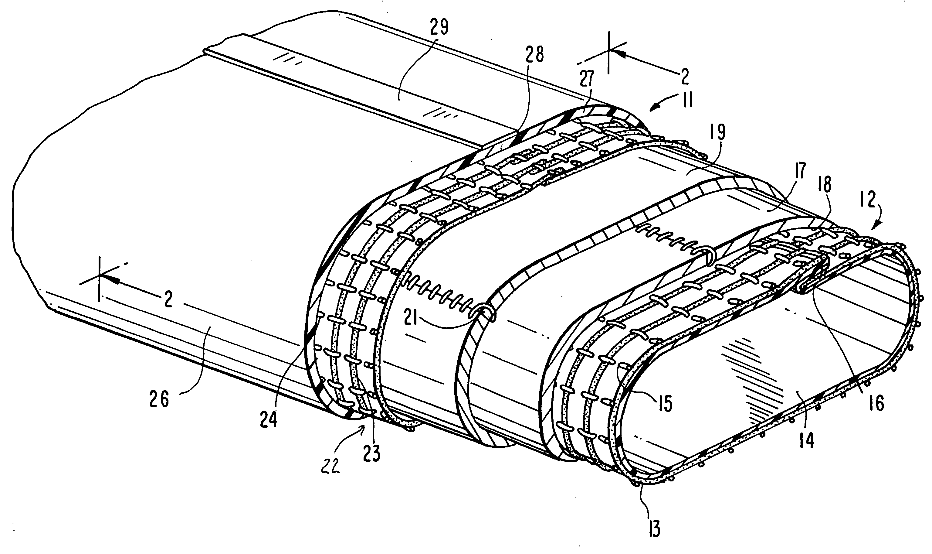
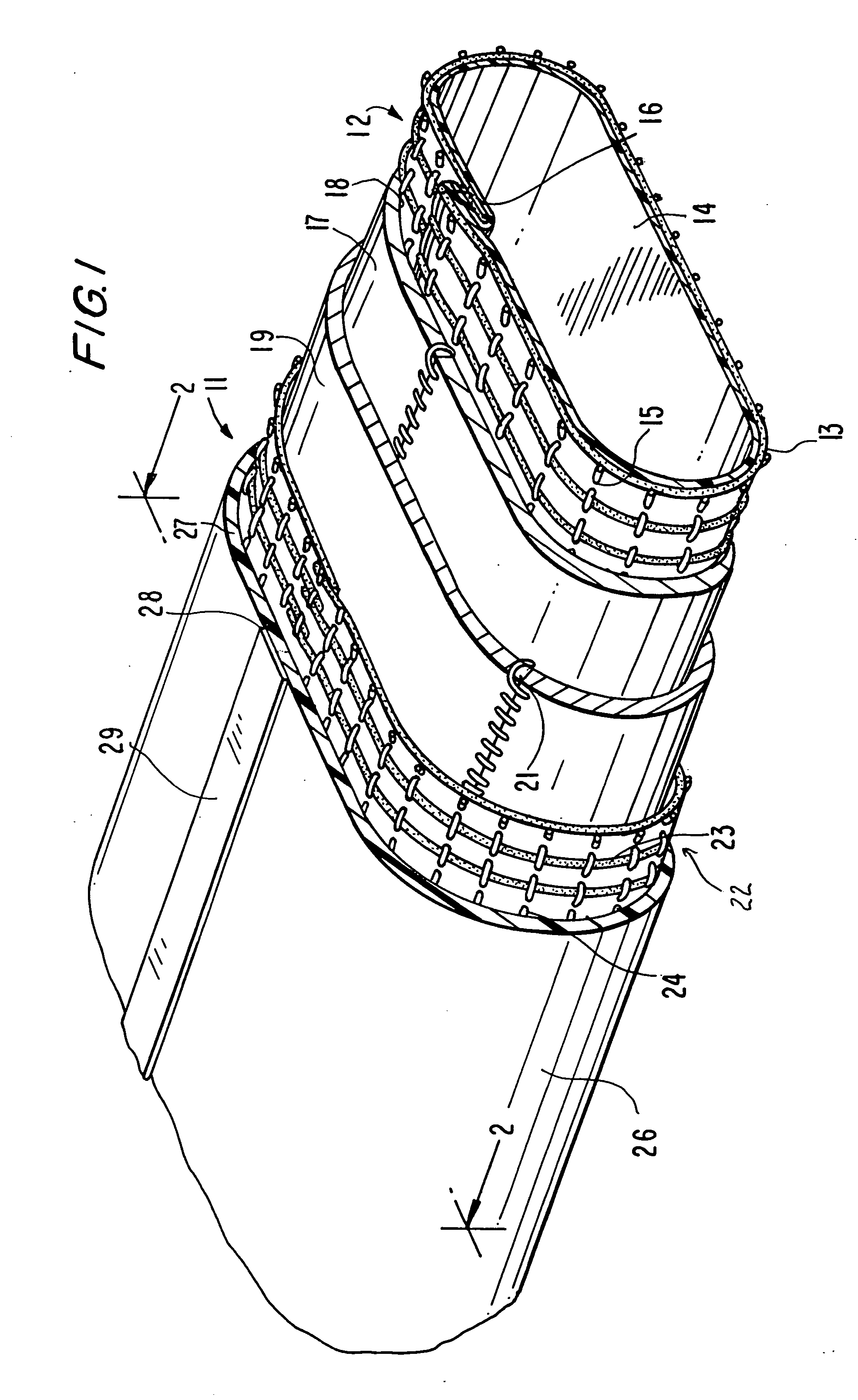
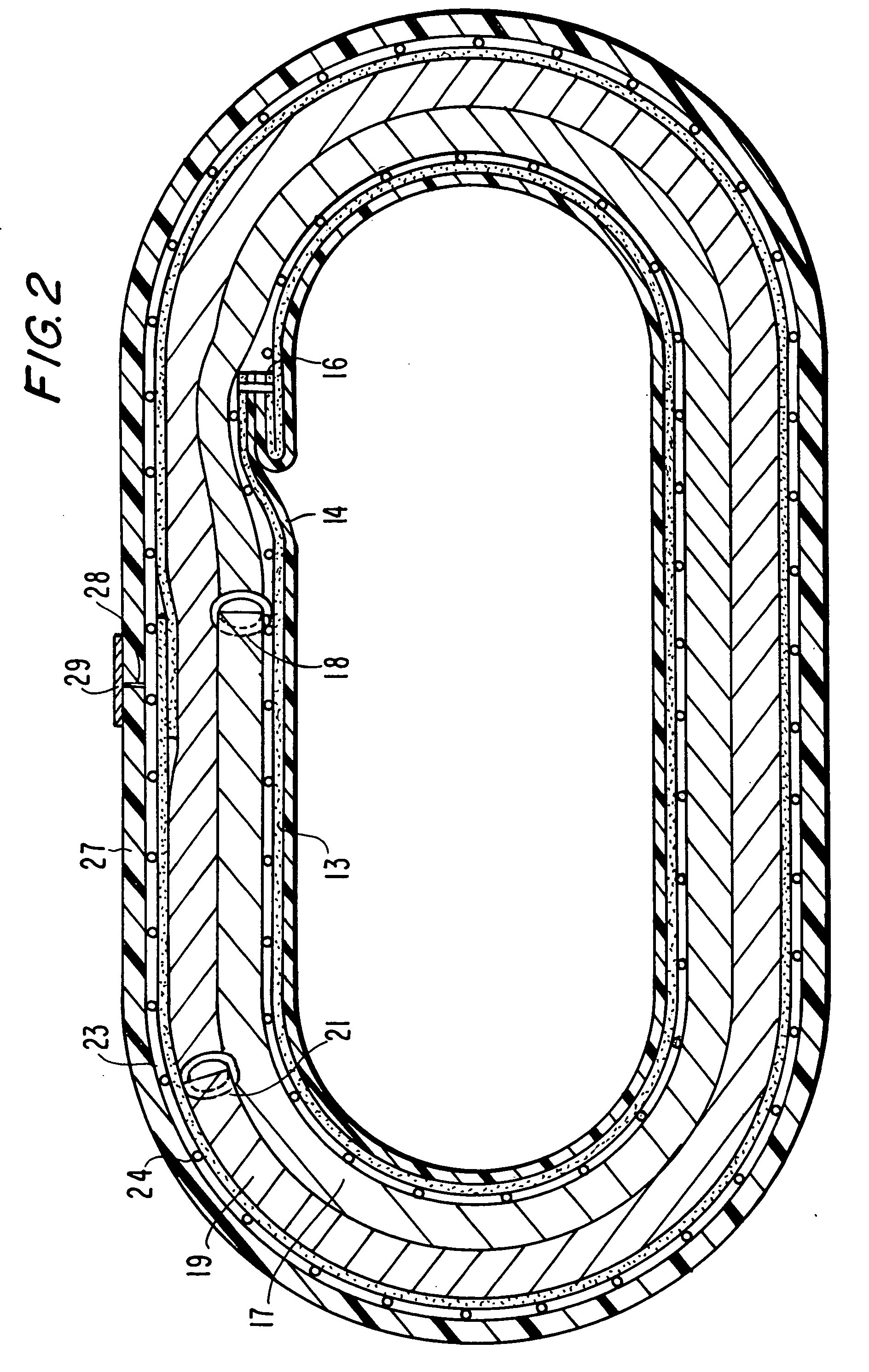
[0036] By incorporating high modulus fibers in the lining structure the flexural and compressive moduli of the lining can be increased so that thinner linings can be used for a given design pressure. Such reinforcing fibers may be arranged in one axis, in one plane or randomly in all three axes (as with standard felt), but the volume fraction of the reinforcement is minimized and the axial modulus and strength are maximum when the fibers are in one axis and reduce rapidly when the other structures are used. Linings require circumferential strength and stiffness so fibers should be aligned in the circumferential direction and the most economical use is in two layers at the outside surfaces.

[0037] The following table compares properties of glass fibers and certain available lower cost carbon fibers.

TABLE IUni-directionalUni-directionalBi-axialPropertyCarbon FiberGlass FiberCarbon + resinGlass + resinGlass + resinTensile450,000350,000182,000161,00080,000Strength psiTensile33,000,000...


PUM

PropertyMeasurementUnit
Lengthaaaaaaaaaa
Diameteraaaaaaaaaa
Strengthaaaaaaaaaa

Abstract

A reinforced liner for cured in place pipe rehabilitation of an existing pipeline having a plurality of high-strength low-elongation fiber bundles disposed circumferentially around the tubular liner at both inner and outer surfaces of a resin absorbent layer of the liner is provided. The bundles of reinforcing fibers are continuous lengths of high modulus fibers laid circumferentially with the ability to stretch to accommodate variations in host pipe diameter. The fibers on the inner surface are secured to a porous scrim to form an inner tubular reinforcing layer. A resin absorbent layer is formed into a tube about the inner layer. An outer layer of bundles of reinforcing fiber are formed into a tube about the absorbent layer. An outer impermeable tubular layer is wrapped around the inner layers. The reinforcing layer may include longitudinal reinforcing fiber in either or both reinforcing layers to increase the longitudinal strength of the liner.

Description

BACKGROUND OF THE INVENTION [0001] This invention relates to a fiber reinforced composite liner of flexible resin absorbent material, and more particularly to a composite liner having bundles of high-strength low-elongation fiber layers disposed circumferentially around the tubular liner adjacent to both inner and outer surfaces of the liner with at least one layer of resin absorbent material between the fiber reinforcing layers to increase the resistance to buckling of the cured liner. [0002] It is generally well known that conduits or pipelines, particularly underground pipes, such as sanitary sewer pipes, storm sewer pipes, water lines and gas lines that are employed for conducting fluids frequently require repair due to fluid leakage. The leakage may be inward from the environment into the interior or conducting portion of the pipelines. Alternatively, the leakage may be outward from the conducting portion of the pipeline into the surrounding environment. In either case, it is d...

Claims


Application Information

Patent Timeline
IPC IPC(8): F16L55/165
CPCF16L55/1656F16L55/1651
Inventor SMITH, E. PETER
Owner INA ACQUISITION
Why Eureka
Try Eureka