[0008] One
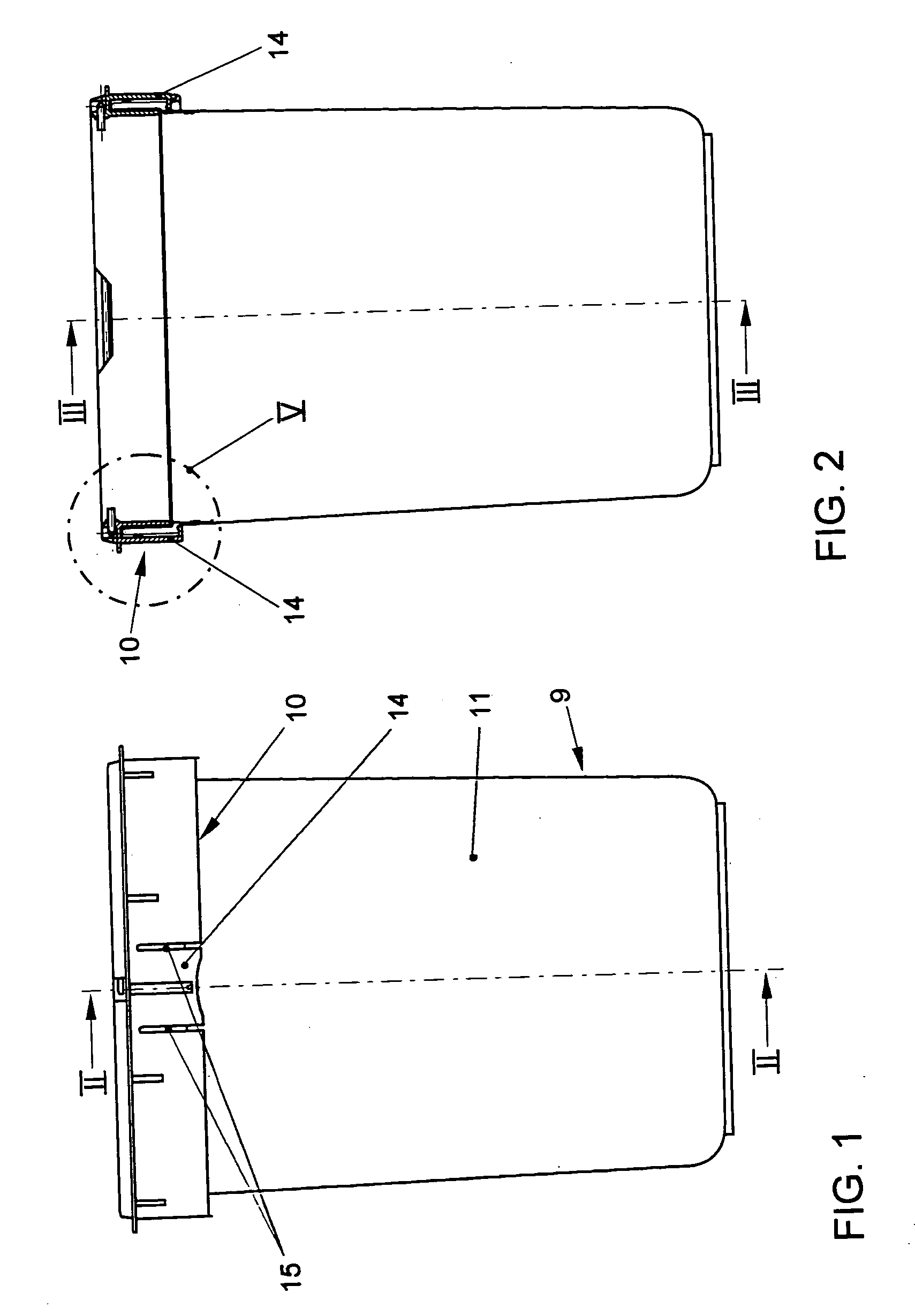
advantage of the invention resides in the fat that the garbage bag can be fastened in such a manner to the receptacle by means of the ring, which can be placed on it that, it is concealed to the outside by the ring. The garbage bag therefore disappears in the region of the gap between the ring and the upper edge region of the container. The garbage bag therefore no longer appears outward from the ring in an overlapping region in an unattractive manner.
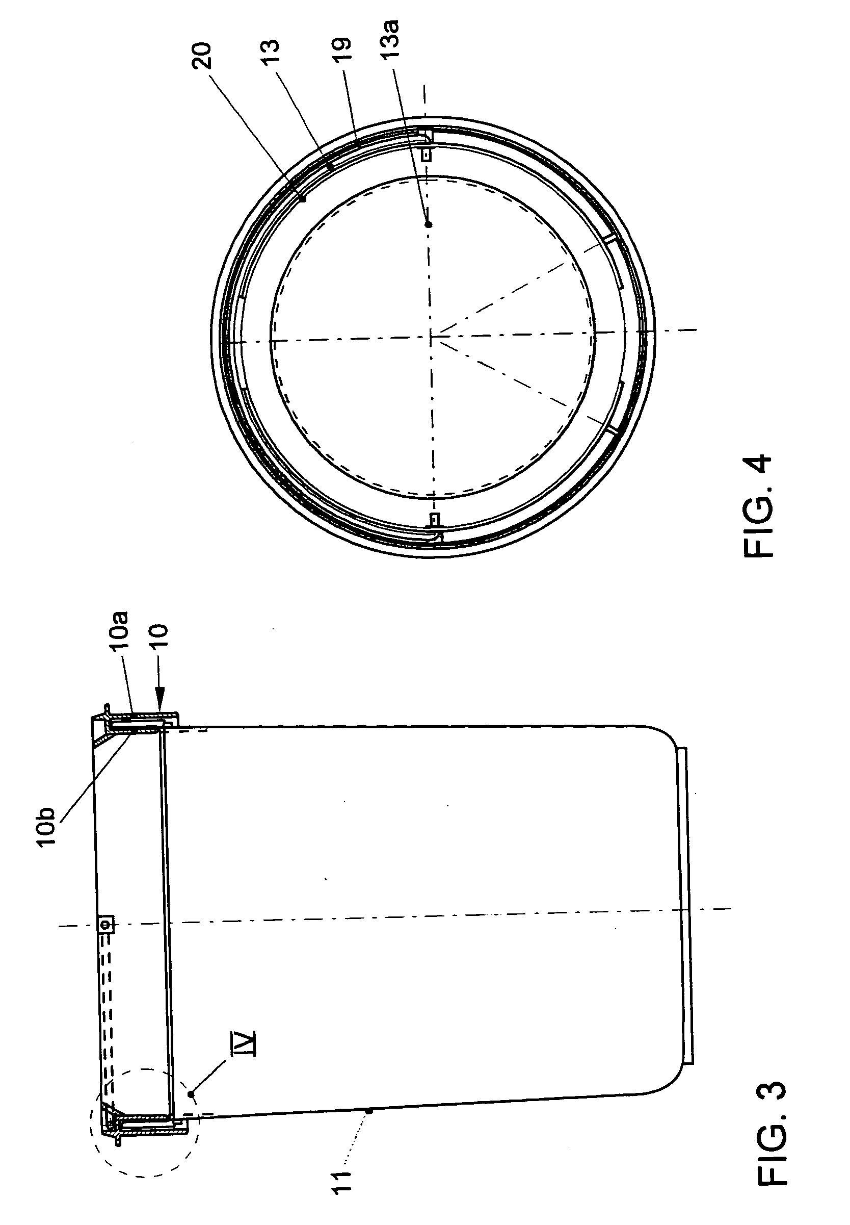
[0009] The ring can be secured in a latching manner in the upper edge region of the receptacle by the fact that the ring has at least one, preferably at least two latching regions, in which it can be connected in a frictional and / or form-fitting manner to an upper section of the receptacle. A latching region of this type may, for example, comprise a latching tongue which is resiliently elastic preferably in approximately the radial direction. A latching tongue of this type may, for example, be made resiliently elastic by the fat that the incisions are provided on both sides of the latching region so that the tongue lies freely at the lower end and is therefore somewhat movable approximately in the radial direction. In this case, this latching tongue an be somewhat under prestress in the radial direction because of the stress of the material, and so the latching tongue, when pushed onto the upper edge region, i.e. the lathing region of the container, virtually snaps onto the latter.
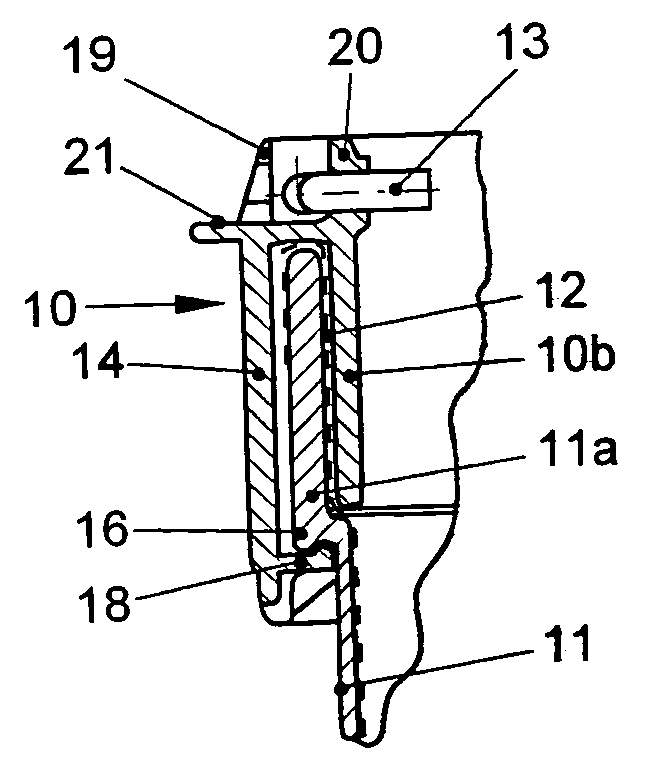
[0010] One preferred development of the invention makes provision for a step to be formed on the receptacle at a distance below the upper edge. In this case, the latching region of the ring can be snapped over this step when being latched into place. The receptacle preferably has, in the region of the step, an
undercut which is situated radially further inward. If the latching region has, in the lower end region, an angled section which is directed radially inward, said angled section can snap over the step into the
undercut, thus resulting in a particularly secure connection which prevents he ring from being lifted off upward even if a tensile force is exerted. A tensile force of this type is exerted if the receptacle is used as an inner bucket an is lifted up at a hoop, which, as has been described above, is attached, for example, to the ring. In one structural solution of the latching connection of the abovementioned type, the entire receptacle can readily be lifted up by means of a hoop which is situated on the ring.
[0011] A hoop of this type generally lies horizontally when not in use and is then pivoted up about a
horizontal axis if it is desired to lift of the refuse bin, or the receptacle, which is an inner bucket for a refuse container. When not in use, the hoop can be deposited onto parts of the ring. For this purpose, corresponding regions can be integrally formed on the ring, between which the hoop can be deposited. For example, at least partially annular, concentric, upwardly protruding ring ribs can be formed on the upper side of the ring.
[0012] As a rule, the outer ring leg is connected to the inner ring leg by a web running at right angles to the latter. When the ring is placed on, this web can rest on the upper edge of the container and can therefore provide a support for the ring and a type of stop when pushing the ring on for the purpose of fastening it on the upper edge region of the receptacle. Moreover, a web-like, approximately horizontal supporting region can be provided, for example, on the ring, which region extends radially further outward, so that, for example, a lid of a refuse bin can be placed on there. When there are two vertical, parallel rig legs, the inner ring leg can be somewhat shorter than the outer ring leg. In this case, the outer ring leg preferably covers the abovementioned step of the receptacle.

