Method of assembling ink jet head unit

Inactive Publication Date: 2005-03-24
RISO KAGAKU CORP
View PDF1 Cites 35 Cited by
  • Summary
  • Abstract
  • Description
  • Claims
  • Application Information

AI Technical Summary

Benefits of technology

[0025] With this method, the plural ink jet heads are positioned by the common positioning unit. That is, a plurality of positioning units is not used to position the plural ink jet heads. The common positioning unit which is different from the individual positioning units needs not individual positioning operations for the plural ink jet heads. Therefore, the common positioning unit can position the plural ink jet heads more accurately than in a case that the individual positioning units pos

Problems solved by technology

However, it is difficult to accurately stick th

Method used


Image

  • Method of assembling ink jet head unit
  • Method of assembling ink jet head unit
  • Method of assembling ink jet head unit

Examples


Example

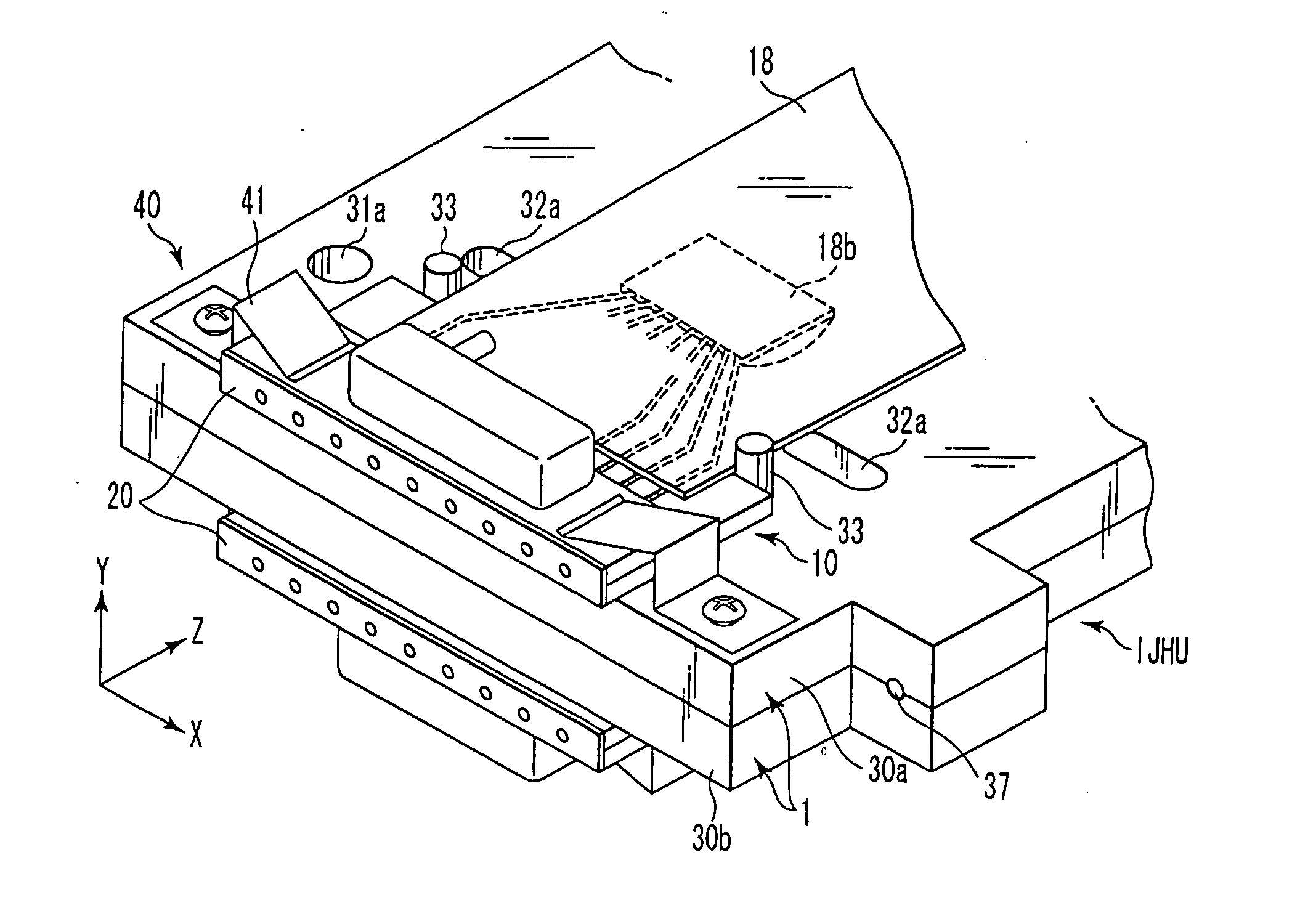
[0084] At first, a first embodiment of an ink jet head unit IJHU will be described with reference to FIGS. 1 to 5.

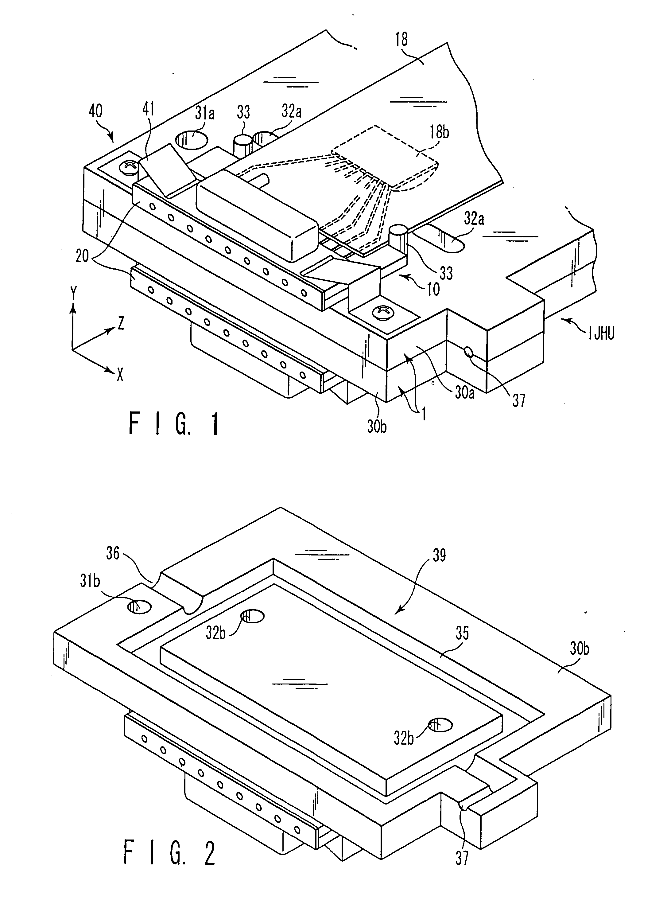
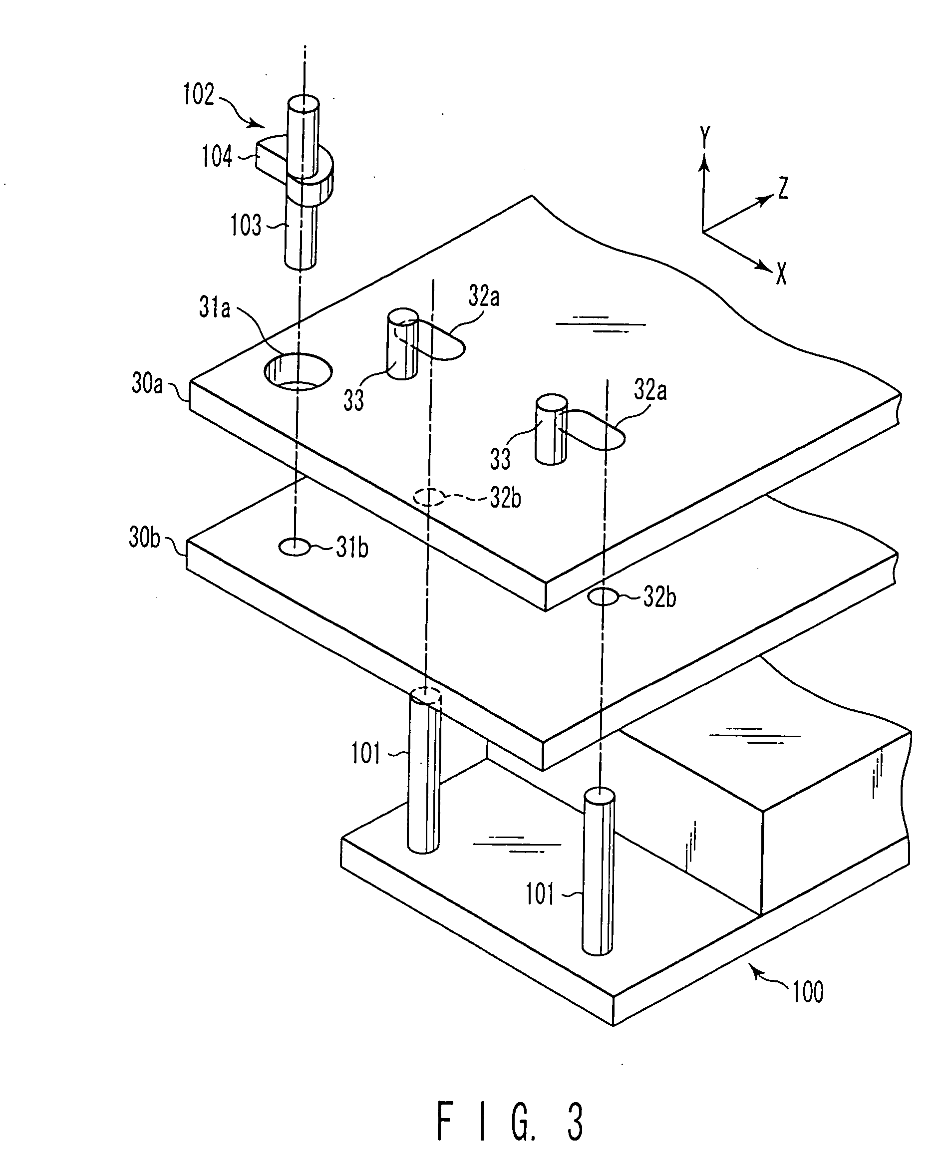
[0085]FIG. 1 is a perspective view of the ink jet head unit IJHU of the embodiment. FIG. 2 is a perspective view showing a shape of a bottom surface of a second base plate of the ink jet head unit IJHU. FIG. 3 is a perspective view showing a positional relation among two base plates, an adjustment base, and a cam member in the ink jet head unit IJHU. FIG. 4 is a sectional view showing ink jet heads of FIG. 1 while a positional adjustment between them in a Z direction is performed. FIG. 5 is a partially sectioned front view of the ink jet head of FIG. 1 while a positional adjustment between them in an X direction is performed.

[0086] The ink jet head unit IJHU has two ink jet heads 1. Each ink jet head 1 includes an ink ejecting portion provided with a piezoelectric member 10 for ejecting ink, and a base plate to which the ink ejecting portion is fixed. The ink jet head ...

Example

SECOND EMBODIMENT

[0129] Next, an ink jet head unit IJHU according to a second embodiment will be described with reference to FIGS. 10 to 12.

[0130] (Constitution)

[0131]FIG. 10 is a perspective view of the ink jet head unit according to the embodiment. FIG. 11 is a sectional view showing ink jet heads 1 of FIG. 10 while a positional adjustment between them in a Z direction is performed. FIG. 12 is a partially sectioned front view of the ink jet heads 1 of FIG. 10 while a positional adjustment between base plates of them in an X direction is performed. In this embodiment, components similar to those in the first embodiment are denoted by the same reference numerals as those denoting the similar components in the first embodiment, and descriptions thereof will be omitted.

[0132] The ink jet head unit IJHU of the embodiment is different from that of the first embodiment in the following constitution. In the ink jet head unit IJHU of the embodiment, no pins for Z-direction positioning ...

Example

THIRD EMBODIMENT

[0146] Next, an ink jet head unit IJHU according to a third embodiment will be described with reference to FIGS. 13 to 18.

[0147] (Constitution)

[0148]FIG. 13 is a perspective view of the ink jet head unit IJHU of this embodiment. FIG. 14 is a top view of the ink jet head unit IJHU of FIG. 13. FIG. 15 is a perspective view showing a positional relation among a base plate, an adjustment base, and a cam member in the ink jet head unit IJHU of FIG. 13. FIG. 16 is a sectional view showing ink jet heads of FIG. 13 while a positional adjustment between them in a Z direction is performed. FIG. 17 is a partially sectioned front view of the ink jet heads of FIG. 13 while a positional adjustment between them in an X direction is performed. FIG. 18 is a schematic view showing the ink jet head unit of FIG. 13 mounted to an image recording apparatus.

[0149] The ink jet head unit IJHU of this embodiment is different from that of the first embodiment in the following constitution....


PUM


Abstract

A method of assembling an ink jet head unit, according to the present invention, is used to assemble the ink jet head unit configured by fixing a plurality of ink jet heads such that one ink jet head is fixed to the other ink jet head adjacent thereto, each ink jet head having an ink ejecting portion in which a plurality of nozzles to eject ink are arrayed. In this method, the ink jet heads are positioned by abutting the ink jet heads on a common positioning unit, and the plurality of ink jet heads are fixed such that one ink jet head is fixed to the other ink jet head adjacent thereto, in a state that the ink jet heads are so positioned as described above.

Description

CROSS-REFERENCE TO RELATED APPLICATIONS [0001] This is a Continuation Application of PCT Application No. PCT / JP03 / 03657, filed Mar. 25, 2003, which was published in Japanese. [0002] This application is based upon and claims the benefit of priority from prior Japanese Patent Application No. 2002-084121, filed Mar. 25, 2002, the entire contents of which are incorporated herein by reference.BACKGROUND OF THE INVENTION [0003] 1. Field of the Invention [0004] The present invention relates to a method of assembling an ink jet head unit of a laminated structure in which two ink jet heads each having the same structure as to each other are stuck together, and more particularly to a method of assembling an ink jet head unit which can accurately stick two ink jet heads together. [0005] 2. Description of the Related Art [0006] An image recording apparatus for recording images has widely been known. There are various types of image recording apparatuses. For example, an image recording apparatu...

Claims


Application Information

Patent Timeline
IPC IPC(8): B41J2/14B41J2/145
CPCB41J2/14209B41J2/145B41J2202/20B41J2202/08B41J2202/19B41J2002/14491B41J2/16532
Inventor KITAHARA, TOSHIHIROHASHIMOTO, TATSUTOSHIHASHI, HIROSHIYOKOYAMA, NORIKO
Owner RISO KAGAKU CORP
Why Eureka
Try Eureka