
Model based positioning system

Active Publication Date: 2008-06-26
MICROPOS MEDICAL
View PDF11 Cites 10 Cited by
  • Summary
  • Abstract
  • Description
  • Claims
  • Application Information

AI Technical Summary

Benefits of technology

[0006]An object with the present invention is to provide a positioning system that more accurately may determine the position and orientation of a positioning device when arranged within a body.
[0010]An advantage with the present invention is that a fast and accurate position of a positioning device may be obtained compared to prior art systems.
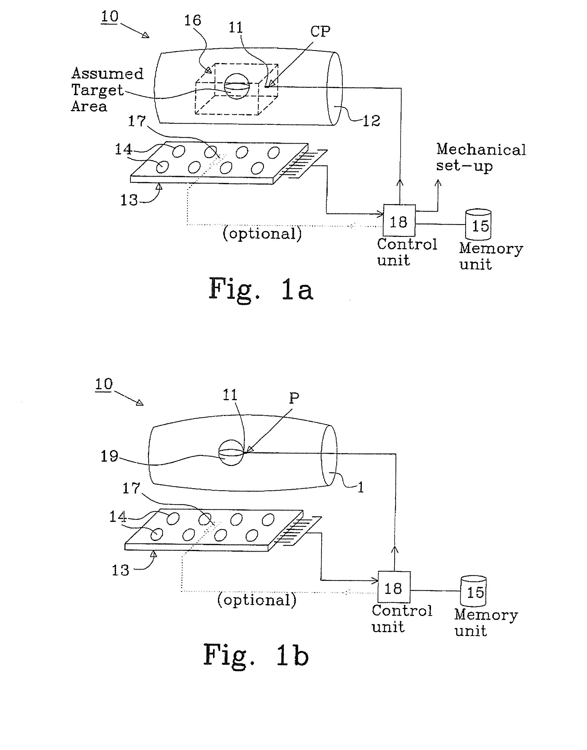
[0011]An advantage with a preferred embodiment is that a continuous performance verification process may be achieved by providing a reference transmitter arranged at a predetermined distance from each receiver element. A reference transmit signal is transmitted from the reference transmitter and a receive signal is measured at each receiving element, wherein the measured receive signal is weighted to coincide with a reference model obtained earlier.

Problems solved by technology

The adjustment is rather coarse, and thus the accuracy of the positioning system is limited.
Furthermore, the performance verification process is time consuming and a complex process that will occupy the radiotherapy equipment at regular intervals, which in turn will reduce the number of patients that could have been treated.

Method used


Image

  • Model based positioning system
  • Model based positioning system
  • Model based positioning system

Examples


Embodiment Construction

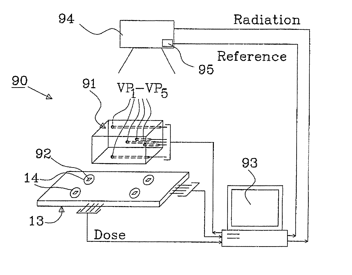
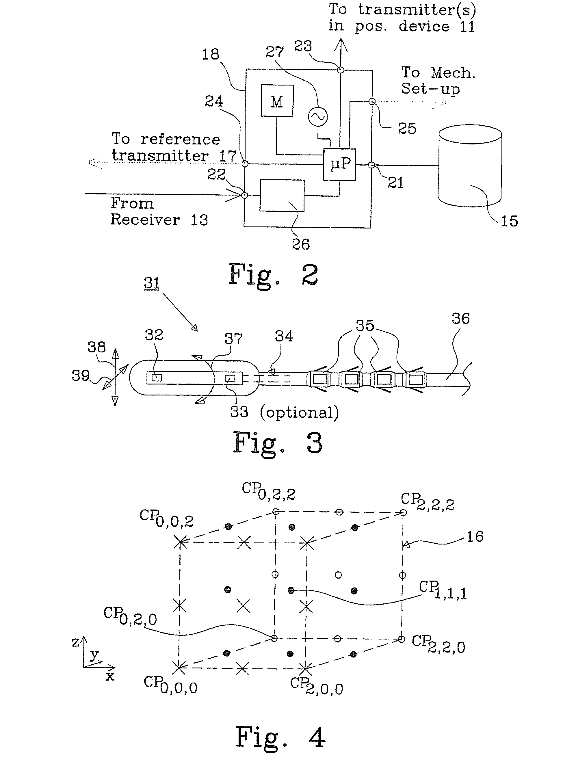
[0026]The detailed description will describe a model based positioning system that operates in two different modes. In a first mode, calibration mode, a model is built that reflects the impact of each receiver element when arranging a positioning device in an arbitrary position, and in a second mode, tracking mode, the built model is used to estimate the position of the positioning device.

[0027]A theoretical model could be built to allow direct calculation of the position of the positioning device from input data. However, this model will be quite complex in order to take all second order effects into consideration. Also, it requires that all second order effects and disturbances are both known and modeled. Examples of secondary effects are: surroundings (metal objects in the vicinity), mutual coupling between antenna elements, reflections of transmit signal at tissue / air interface, multilayer internal multi reflections (due to multiple tissue with different electrical properties), ...


PUM


Abstract

The present invention relates to a model based positioning system 10; 90 that comprises a positioning device 11; 31 having at least one transmitter configured to be in a tracking environment, e.g. inserted into a body 1, a receiver 13 having a plurality of receiver elements 14 arranged outside the tracking environment, a control unit 18; 93 configured to measure amplitude and / or phase information of a signal transmitted from the at least one transmitter and received at each receiving element, and a memory unit M; 15 for storing a model for each receiving element. The control unit is also configured to estimate the position P of the positioning device by comparing the model for each receiving element with the measured received signal for each receiving element.

Description

TECHNICAL FIELD[0001]The present invention relates to a model based positioning system, especially for a positioning system used in medical applications. The invention also relates to a method for calibrating the positioning system, and a method for tracking a positioning device within a body using the positioning system.BACKGROUND[0002]Several positioning systems exist today, that are used to determine a three-dimensional position of an implantable positioning device in a body. These positioning systems are particularly suited for tracking the position of a cancer area for radiation therapy (radiotherapy).[0003]One type of system is based on radio frequency transmission from an implantable positioning device acting as a transmitter to an externally arranged receiver, as described in the international patent application PCT / SE2006 / 001135, assigned to Micropos Medical AB, which is hereby incorporated as reference. The transmitter transmits an electromagnetic signal at a specified fre...

Claims


Application Information

Patent Timeline
IPC IPC(8): A61B5/05G01S5/02
CPCA61B5/05A61B5/06G01S5/021A61N2005/1051A61N5/1049A61B2034/2051A61B2034/2065A61B5/062A61B34/20G01S5/14G01S11/06H04B17/21A61B2560/0228A61B2560/0238
Inventor IUSTIN, ROMANLINDER, JOHANISBERG, ERIKGUSTAFSSON, TOMASLENNERNAS, BO
Owner MICROPOS MEDICAL
Learn More