Environmentally hardened Ethernet switch

a technology of ethernet switches and environment hardening, which is applied in the direction of data switching details, data switching current supply, instruments, etc., can solve the problems of prior art ethernet switches not meeting these standards, prior art devices that do not meet at least the following criteria, switches are susceptible to electrical transients, etc., to achieve high degree of electrical resistance, increase system reliability, and the effect of high mtb

Inactive Publication Date: 2005-06-09
SIEMENS CANADA LTD
View PDF9 Cites 13 Cited by
  • Summary
  • Abstract
  • Description
  • Claims
  • Application Information

AI Technical Summary

Benefits of technology

[0024] One advantage of the present invention is that the circuit for use in the Ethernet Switch has a high degree of resistance to electrical transient effects and electromagnetic interferences. In particular, the circuit provides transient suppression of electrical signals entering into the power supply. This is accomplished in a preferred embodiment by using a combination of transzorbs, metal oxides varistors, and one or more capacitors. Furthermore, the device provides a conversion block for converting electrical signals into fiber optic signals and a fiber optical transmitter / receiver.
[0025] A further advantage of the present invention is that the circuit provides for thermoelectric cooling. Thermoelectric cooling increases the reliability of the system and has a much higher MTBF. Furthermore, the thermoelectric cooling has a larger cooling range such that, by providing one or more thermoelectric cooling blocks, the operating temperature range of the entire circuit can be controlled. Furthermore, in a preferred embodiment, the thermoelectric cooling can have a heat sink with an extension which extends outside of the switch and / or the utility station enclosure, thereby facilitating removal of thermal energy from the enclosure, and cooling of the entire circuit.

Problems solved by technology

However, the prior art Ethernet switches do not meet these standards.
In particular, the prior art switches do not adhere to the ANSI / IEEE C37.90 standard (US)and the IEC-60255 standard (Europe) which were designed for protective relaying IEDs and other intelligent devices found in electrical substations.
For example, the prior art devices do not satisfy at least the following criteria.
In particular the switch is susceptible to electrical transients and electromagnetic interference being coupled into the device via twisted pair copper cables 8.
This is extremely undesirable since it could result in corruption of real-time mission critical control messages being transmitted over the network via the switch.
Moreover, actual damage to the switch itself is possible if high voltage electrical transients are directly coupled into the device via the copper cables overcoming the limited electrical isolation (typically) 1500 RMS) provided by isolation transformers 5b.
This is not a requirement for commercial grade Ethernet Switches and thus the power supply inputs 6a do not provide suitable transient suppression circuitry.
Furthermore, commercial grade Ethernet switches are not specifically designed to withstand EMI (Electromagnetic Interference) levels of 35 V / m as specified by ANSI / IEEE C37.90.2 (1995) which is typical of the substation environment.
Accordingly, conventional circuit 10 suffers from the disadvantage that it is susceptible to electrical transients and electromagnetic interference at levels which are possible, or even common, in utility substation environment.
The design of FIG. 1 is also susceptible to mechanical breakdown because of the use of rotating cooling fan 7 required to cool the electronic components.
However, the operating temperature range for devices in the substation environment such as protective relays is specified by the IEC 60255-6 (1998) standard as −25° C. to +55° C. Therefore, not only is the circuit 10 of FIG. 1 susceptible to failure, it also does not meet the requirements of the environmental conditions which are possible, or even common in utility substation environments.

Method used


Image

  • Environmentally hardened Ethernet switch
  • Environmentally hardened Ethernet switch
  • Environmentally hardened Ethernet switch

Examples


Embodiment Construction

[0033] A preferred embodiment of the present invention and its advantages can be understood by referring to the present drawings. In the present drawings, like numerals are used for like corresponding parts of the accompanying drawings.

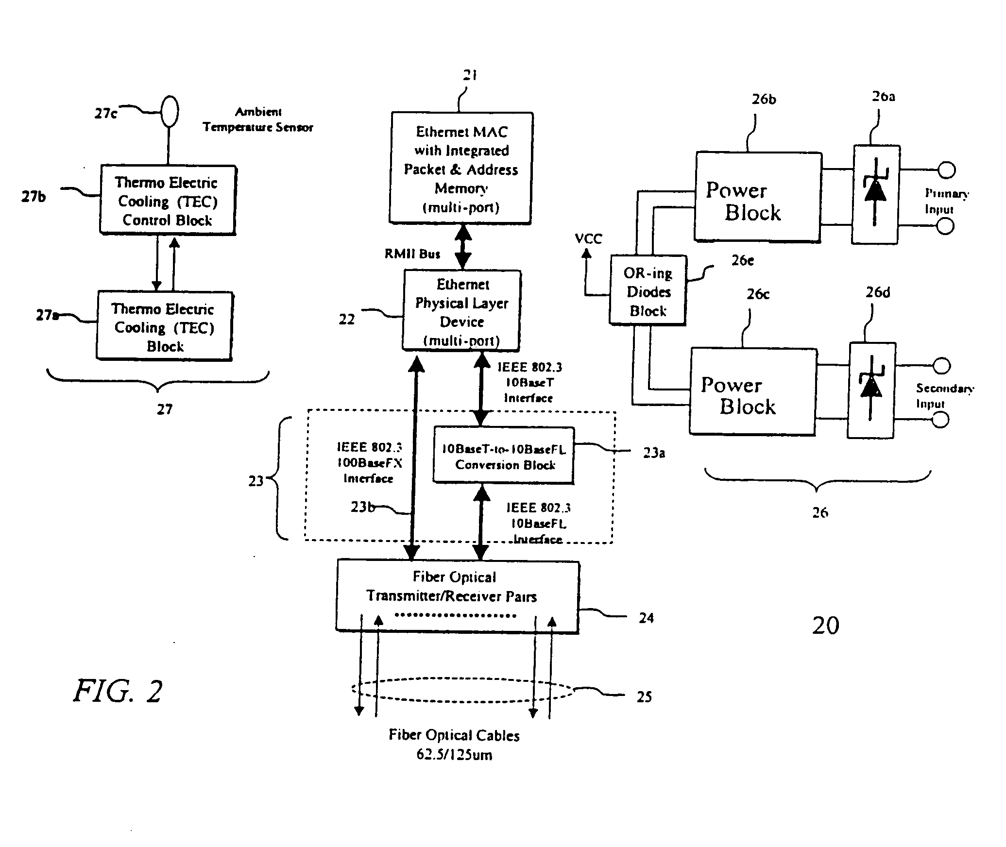
[0034]FIG. 2 illustrates an electronic circuit block diagram shown generally by reference numeral 20, for an Ethernet switch according to one embodiment of the present invention. The circuit consists of an Ethernet Media Access Controller (MAC) block 21 with integrated packet and address memory which provides a plurality of communications ports each adhering to the RMII (Reduced Media Independent Interfaces) signaling specification as put forth by the version 1.2 of the RMII Consortium. Such a block 21 may be implemented using Marvell 88E6050 or a Galileo GT48350.

[0035] These RMII ports interface to a multi-port physical layer device 22, referred to as a PHY, which converts the RMII signals to differential transmit and receive signal pairs in accord...


PUM


Abstract

A device for hardening an Ethernet switch is disclosed. The device provides cooling for the switch, and, suppresses electrical transients and electromagnetic interference, which could affect the power supply, and data transmission of the Ethernet switch. Using this device, the Ethernet switch can be used in harsh industrial environments, such as those present in power utility substations.

Description

[0001] This application is a continuation application of application Ser. No. 10 / 330,148 filed Dec. 30, 2002, now abandoned.FIELD OF THE INVENTION [0002] The present invention relates in general to the field of computer communication networks and specifically to Ethernet switching hubs (Ethernet Switch) suitable for use in harsh industrial environments such as those found in electric power utility substations. BACKGROUND OF THE INVENTION [0003] Trends in the electric power utility automation sector, specifically substation automation, have been driving towards common communications architecture. The initiative was begun in the early 1990s driven by the major North American utilities under the technical auspices of Electric Power Research Institute (EPRI). The resulting standard that emerged is known as the Utility Communications Architecture 2.0 (UCA2). At the heart of this architecture is the substation LAN (Local Area Network) based on Ethernet. However, one of the major requireme...

Claims


Application Information

Patent Timeline
Patent Type & Authority Applications(United States)
IPC IPC(8): G06F1/18G06F1/20H05K7/10H05K9/00
CPCG06F1/182G06F1/20H04L49/351H05K7/1092H05K9/0066H04L12/10
Inventor POZZUOLI, MARZIO PARIDE
Owner SIEMENS CANADA LTD
Why Eureka
Try Eureka