Floor covering and locking systems

a technology of locking system and floor covering, which is applied in the direction of load-supporting elements, structural elements, building components, etc., can solve the problems of large load on the locking system, continuous floor surface must as a rule be limited, and the load is particularly great in the passage between different rooms, so as to achieve better precision

Active Publication Date: 2005-08-04
VÄLINGE INNOVATION AB
View PDF99 Cites 260 Cited by
  • Summary
  • Abstract
  • Description
  • Claims
  • Application Information

AI Technical Summary

Benefits of technology

[0032] A third object of the present invention is to provide equipment and production methods which make it possible to produce floorboards and mechanical locking systems with an end tenor but with better precision than what is possible to accomplish with known technology.
[0033] Equipment for production of building panels, especially floorboards, comprises a chain, a belt, a pressure shoe and a tool set. The chain and the belt are arranged to displace the floorboard relative the tool set and the pressure ...

Problems solved by technology

The drawback is that the continuous floor surface must as a rule be limited even in the cases where the floor consists of relatively dimensionally stable floorboards, such as laminate floor with a fiberboard core or wooden floors composed of several layers with different fiber directions.
Without such a division, it is a risk that the floor when shrinking will change in shape so that it will no longer be covered by baseboards.
Also the load on the locking system will be great since great loads must be transferred when a large continuous surface is moving.
The load will be particularly great in passages between different rooms.
They collect dirt, give an unwanted appearance and are rather expensive.
Due to these limitations on maximum floor surfaces, laminate floorings have only reached a small market share in commercial applications such as hotels, airports, and large shopping areas.
Even if such an installation would be possible, the continuous floor surface must b...

Method used


Image

  • Floor covering and locking systems
  • Floor covering and locking systems
  • Floor covering and locking systems

Examples


Embodiment Construction

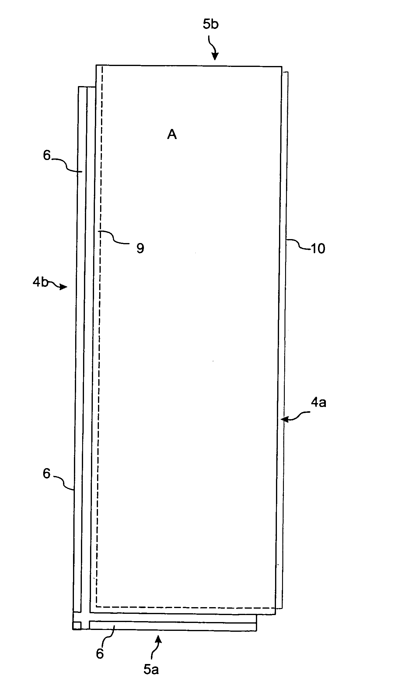
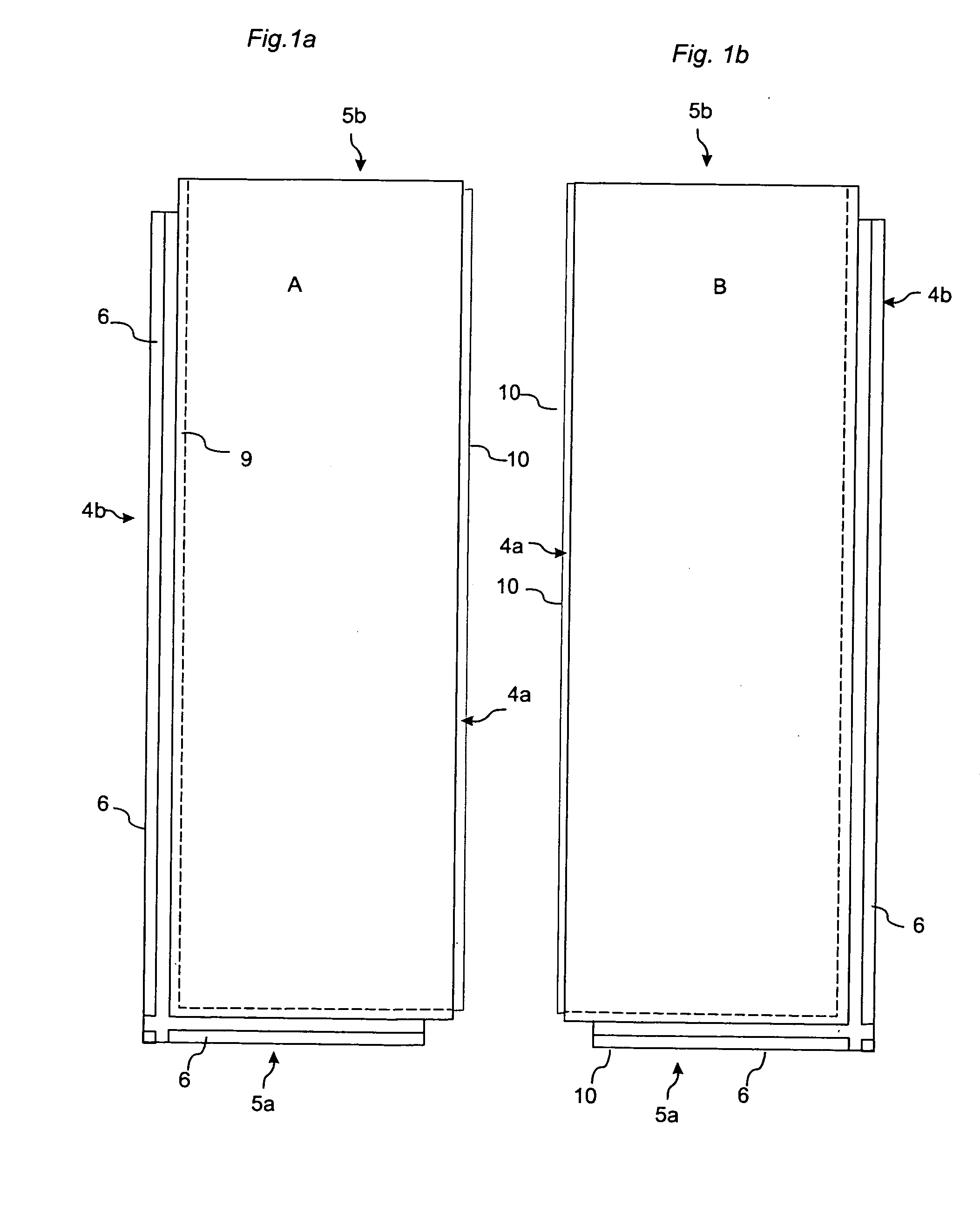
[0048]FIGS. 1a and 1b illustrate floorboards which are of a first type A and a second type B according to the invention and whose long sides 4a and 4b in this embodiment have a length which is 3 times the length of the short sides 5a, 5b. The long sides 4a, 4b of the floorboards have vertical and horizontal connectors, and the short sides 5a, 5b of the floorboards have horizontal connectors. In this embodiment, the two types are identical except that the location of the locks is mirror-inverted. The locks allow joining of long side 4a to long side 4b by at least inward angling and long side 4a to short side 5a by inward angling, and also short side 5b to long side 4b by a vertical motion. Joining of both long sides 4a, 4b and short sides 5a, 5b in a herringbone pattern or in parallel rows can in this embodiment take place merely by an angular motion along the long sides 4a, 4b. The long sides 4a, 4b of the floorboards have connectors, which in this embodiment comprising a strip 6, a...


PUM


Abstract

Floorboards with a mechanical locking system that allows movement between the floorboards when they are joined to form a floating floor.

Description

CROSS-REFERENCE TO RELATED APPLICATIONS [0001] The present application claims priority of Swedish Patent Application No. 0400068-3, filed in Sweden on Jan. 13, 2004 and U.S. Provisional Application No. 60 / 537,891, filed in the United States on Jan. 22, 2004, the entire contents of which are hereby incorporated herein by reference.FIELD OF THE INVENTION [0002] The invention relates generally to the technical field of locking systems for floorboards. The invention concerns on the one hand a locking system for floorboards which can be joined mechanically and, on the other hand, floorboards and floor systems provided with such a locking system and a production method to produce such floorboards. [0003] The present invention is particularly suited for use in floating wooden floors and laminate floors, such as massive wooden floors, parquet floors, floors with a surface of veneer, laminate floors with a surface layer of high pressure laminate or direct laminate and the like. [0004] The fo...

Claims


Application Information

Patent Timeline
IPC IPC(8): B27F5/02B27M3/04E04C3/00E04C3/30E04F15/02E04F15/04
CPCB27F5/026B27M3/04E04F15/02033E04F15/02038E04F15/04E04F2201/05E04F2201/0138E04F2201/0153E04F2201/025E04F2201/026E04F2201/041E04F2201/0115
Inventor PERVAN, DARKO
Owner VÄLINGE INNOVATION AB
Why Eureka
Try Eureka