Ultra high-speed magnetic resonance imaging device

Inactive Publication Date: 2005-09-15
NAT INST OF ADVANCED IND SCI & TECH
View PDF19 Cites 0 Cited by
  • Summary
  • Abstract
  • Description
  • Claims
  • Application Information

AI Technical Summary

Benefits of technology

[0024] (1) In the magnetic resonance imaging equipment, the imaging time T is proportional to the number of phase encodings PE and to the repetition time TR of the individual PE (T=PE×TR). Thus, by decreasing the number PE of phase encodings, it is made possible to decrease the imaging time. This invention, by decreasing the number PE of phase encodings, is enabled to curtail the imaging time and heighten the speed of imaging.
[0025] (2) By estimating the motion of an object to be imaged, it is made possible to complement the unacquired data and reconstruct a two-dimensional or three-dimensional image. Owing to the possession of the characteristic property of being capable of observing a signal at an ultrahigh speed, the temporal [t] change of a magnetic resonance element in an object to be imaged can be grasped. It is consequently made po

Problems solved by technology

Meanwhile, the technique for heightening the speed (shortening the imaging time) results in curtailing the time for instrumentation.
This time requirem

Method used


Image

  • Ultra high-speed magnetic resonance imaging device
  • Ultra high-speed magnetic resonance imaging device
  • Ultra high-speed magnetic resonance imaging device

Examples


Embodiment Construction

[0040] Now, this invention will be described in detail below with reference to the accompanying drawings.

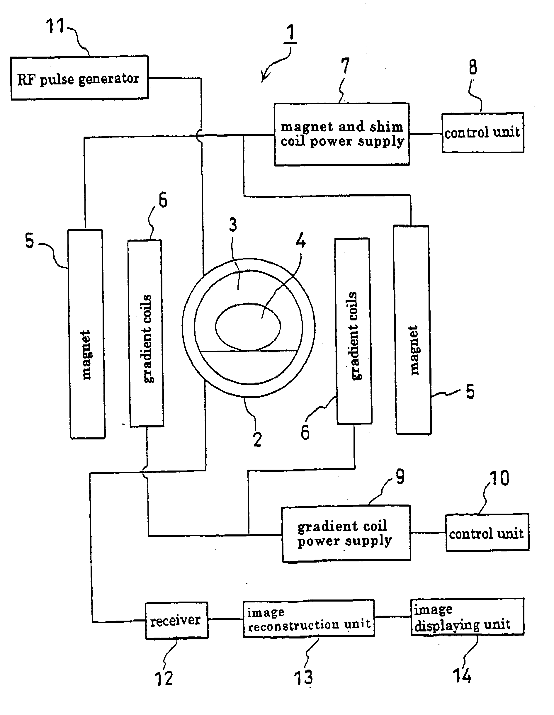
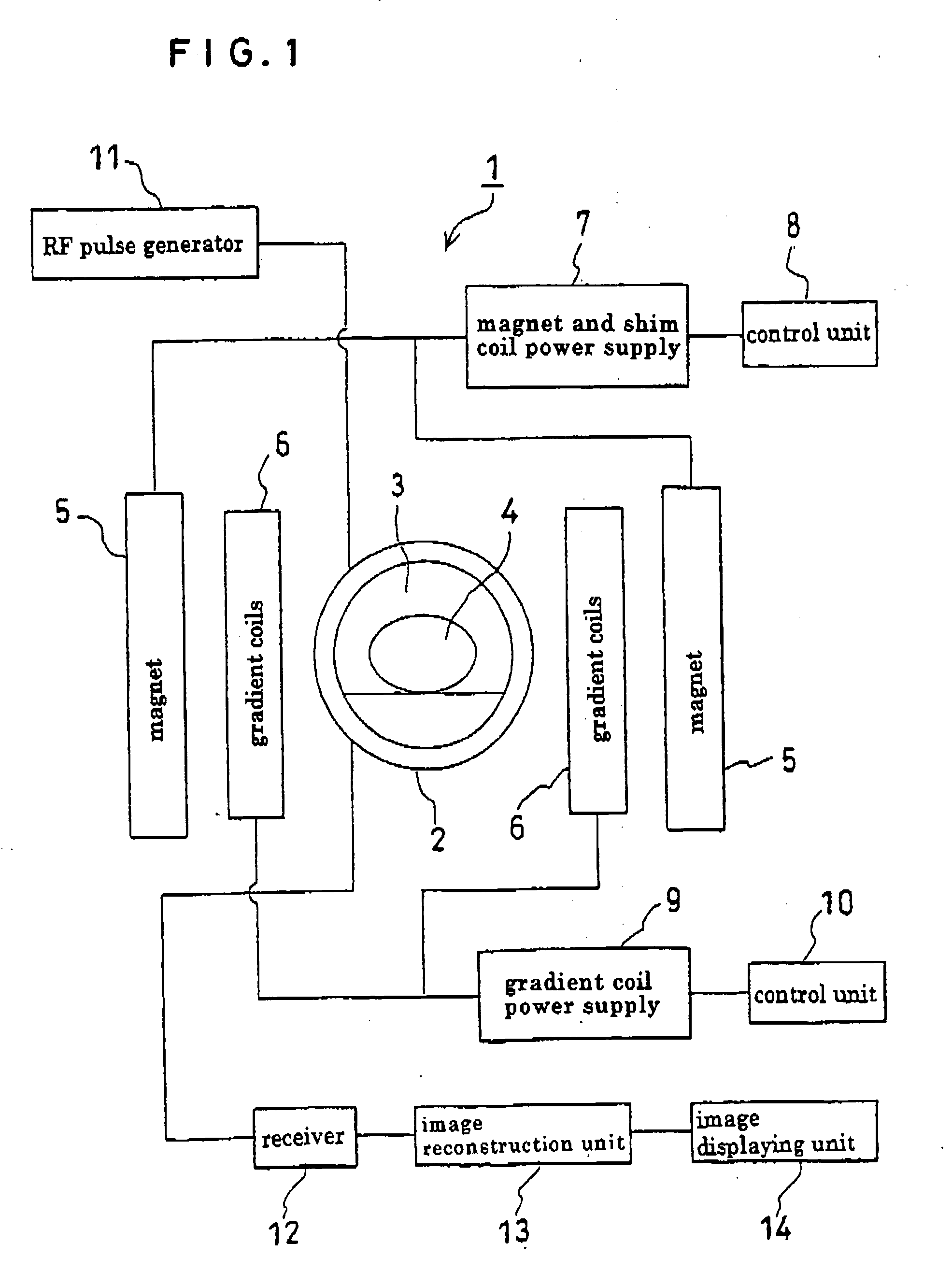
[0041]FIG. 1 shows one example of the ultrahigh speed magnetic resonance imaging equipment for embodying this invention based on the principle of nuclear magnetic resonance. In FIG. 1, an MR imaging equipment 1 is furnished with an excitation and detection unit 2. The excitation and detection unit 2 demarcates a measuring region 3 and excites a substance 4 for measurement in the measuring region 3 as well. To the excitation and detection region 2, an RF pulse (excitation pulse) is supplied from an RF pulse generator 11. This RF pulse possesses a resonance frequency corresponding to the numerous points in the measuring region 3. On the outside of the excitation and detection unit 2, a magnet 5 for generating static magnetic field and gradient coils 6 for generating gradient magnetic field are laid out in a planar state.

[0042] The ultrahigh speed magnetic resonance imaging equipm...


PUM


Abstract

Ultrahigh speed magnetic resonance imaging equipment is capable of predicting temporal and spatial operation of an object to be imaged and significantly reducing the number of phase and frequency encodings, thereby significantly increasing the imaging speed. An object (4) to be imaged is placed in a static magnetic field (3) and a gradient magnetic field and a radiofrequency wave are applied to the object in an x, y and/or z direction in an orthogonal coordinates system. The equipment includes means for collecting only phase and frequency encodings optimized based on an estimate of motion of the object (4) to be imaged and means for complementing unacquired data. By increasing the imaging speed, as described above, the temporal resolution is improved and it is possible to display a two-dimensional cross section and three-dimensional internal structure of the object in motion as an image. As a result imaging is possible even when the object (4) to be imaged is temporally deformed or displaced.

Description

TECHNICAL FIELD [0001] This invention relates to ultrahigh speed magnetic resonance (MR) imaging equipment based on nuclear magnetic resonance (NMR). BACKGROUND ART [0002] The conventional nuclear magnetic resonance imaging (MRI) device is provided on the periphery of an object to be imaged with a magnet for generating a static magnetic field and a gradient magnetic field which is varying temporal and spatial magnetic field intensity (gradient coil), and is consequently enabled to form a spatially uniform magnetic field with the gradient coils. The magnetic resonance imaging is an operation of applying a radiofrequency (RF) wave to an object to be imaged for the purpose of magnetic resonance in a static magnetic field B0 and consequently encoding and imaging the phase and the frequency of a spin in the magnetically resonating atomic nuclei. For the sake of reducing the spatial distribution of the density and the chemical structure of a resonant element, for example, to an image, an ...

Claims


Application Information

Patent Timeline
IPC IPC(8): G01R33/54A61B5/055G01R33/48G01R33/561
CPCG01R33/5619G01R33/561
Inventor HOMMA, KAZUHIRO
Owner NAT INST OF ADVANCED IND SCI & TECH
Why Eureka
Try Eureka