Solar telescope with integrated alignment mechanism

Active Publication Date: 2005-11-10
CORONADO INSTR
View PDF6 Cites 0 Cited by
  • Summary
  • Abstract
  • Description
  • Claims
  • Application Information

AI Technical Summary

Benefits of technology

[0010] According to one aspect of the invention, the targeting image is simply provided by an aperture facing the sun in the housing of the telescope through which sunlight is received and directed to a transmissive viewing screen preferably placed in the housing on the same side of the telescope's eyepiece. Thus, all parts of the targeting system are fixed to the housing of the telescope and removed from accidental contact by personnel operating the telescope, thereby minimizing the chance for events that might cause misalignments. In addition, this configuration makes it possible to use both the viewing screen and the eyepiece without changing position with respect to the telescope.
[0011] According to another aspect of the invention, the relaying optics of the aiming unit inside the telescope housing make it possible to easily fold the targeting beam in any desirable direction. Therefore, when the eyepiece of the telescope is set to the side of the objective's optical axis, as is often the case for the user's comfort, the targeting beam can also be easily folded and directed toward a screen adjacent to the eyepiece. Moreover, since in these cases the telescope housing has necessarily been modified to accommodate the optics required to fold the objective beam toward the eyepiece, the same housing space can be used advantageously to also fold the targeting beam.

Problems solved by technology

Because the angular size of the sun, viewed from the earth, is about 0.5°, pointing a solar telescope with a commensurate field of view precisely towards the sun is not an easy task.
This difficulty is further exacerbated by the fact that the user of the telescope cannot look directly at the sun without harming his or her eyes.
However, this type of alignment is often not sufficiently precise because of the small angles subtended by the sun.
This configuration suffers from several problems that over time tend to affect the performance of the aiming mechanism.
First, from a mechanical point of view, the exterior attachment of the aiming unit to the housing of the telescope subjects it to unavoidable bumps and other stressing forces applied by users that cause misalignments of the unit's optical axis with respect to that of the telescope.
This is often unfortunate because the sun's brightness makes it difficult to identify and follow the image formed on the aiming unit's viewing screen.

Method used


Image

  • Solar telescope with integrated alignment mechanism
  • Solar telescope with integrated alignment mechanism
  • Solar telescope with integrated alignment mechanism

Examples


Embodiment Construction

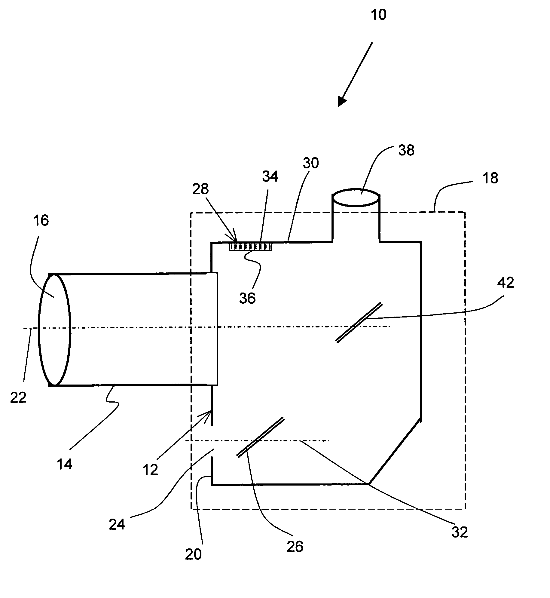
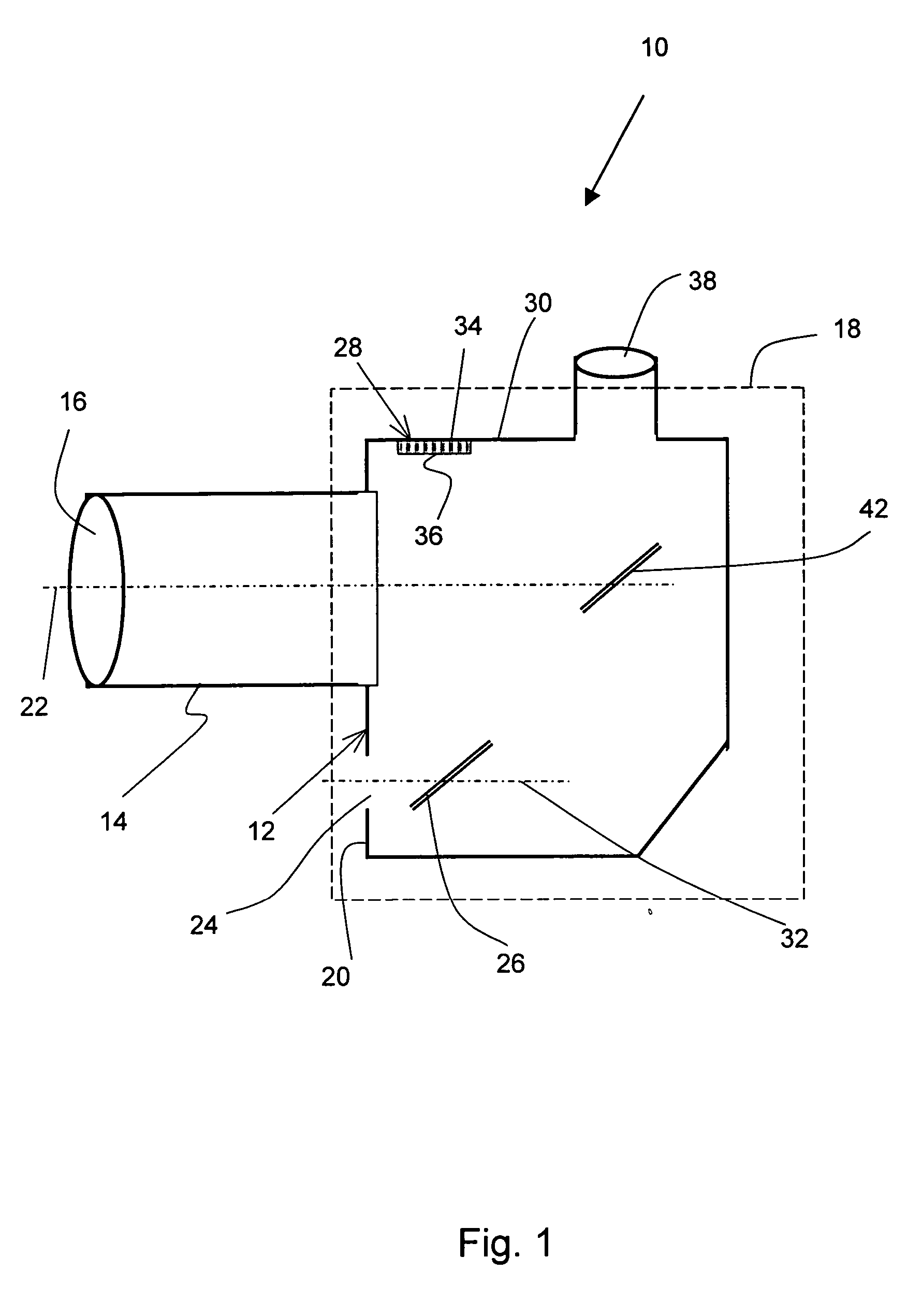
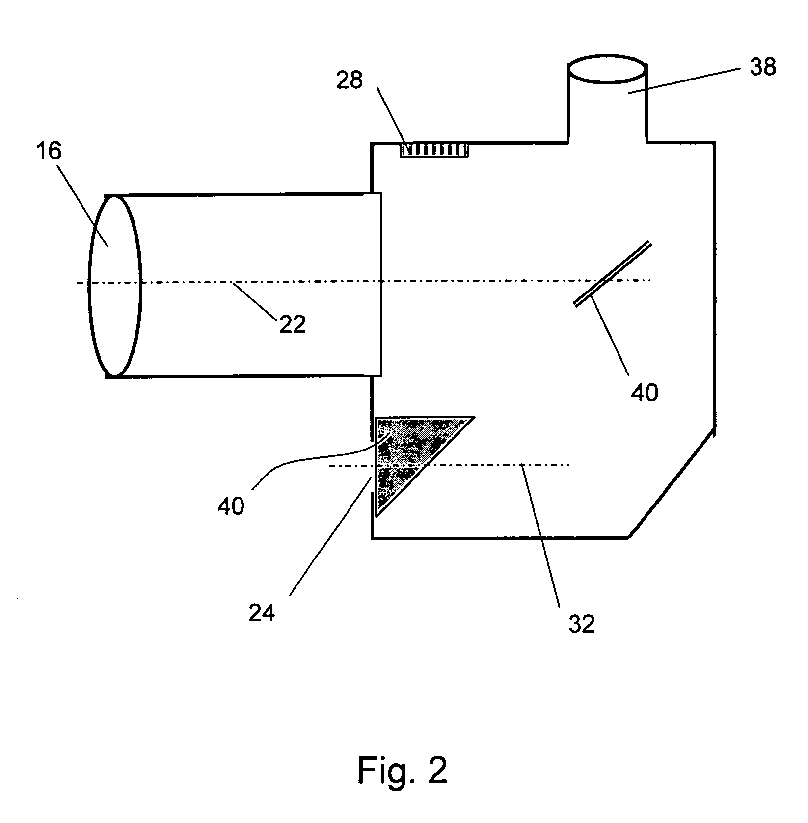
[0017] This invention evolved from a need to provide a targeting mechanism for solar telescopes that is not subject to the lack of precision and / or the susceptibility to misalignments found in prior-art solutions. In essence, these shortcomings are corrected by integrating the targeting system within the housing of the telescope. Various embodiments provide different additional advantages that may be of particular interest for specific applications.

[0018] As used herein, the terms “housing” and “frame” are used interchangeably with reference to telescopes to refer to the outer structural shell that houses the objective, eyepiece and internal optics of a telescope. Conventional housings are typically cylindrical tubes, often of telescopic construction, but no particular shape is intended to be inferred by these terms. In particular, the housings of the present invention are expected to take different shapes depending on the placement of the viewing screen. The term “viewing screen” ...


PUM


Abstract

A targeting unit is incorporated into the main body of a solar telescope. The targeting image is provided by an aperture facing the sun in the housing of the telescope through which sunlight is received and directed to a transmissive viewing screen placed in the housing on the same side of the telescope's eyepiece. All parts of the targeting system are fixed to the housing of the telescope and removed from accidental contact by personnel operating the telescope, thereby minimizing the chance for events that might cause misalignments. In addition, this configuration makes it possible to easily position both the viewing screen and the eyepiece on the same side of the telescope following any degree of folding of the objective beam.

Description

RELATED APPLICATIONS [0001] This application is based on U.S. Provisional Application Ser. No. 60 / 569,480, filed May 06, 2004.BACKGROUND OF THE INVENTION [0002] 1. Field of the Invention [0003] This invention is related in general to the field of solar telescopes. In particular, it relates to a targeting system integrated within the body of a solar telescope. [0004] 2. Description of the Related Art [0005] Solar telescopic observation requires that the objective of the telescope be precisely aligned with the sun. Because the angular size of the sun, viewed from the earth, is about 0.5°, pointing a solar telescope with a commensurate field of view precisely towards the sun is not an easy task. This difficulty is further exacerbated by the fact that the user of the telescope cannot look directly at the sun without harming his or her eyes. [0006] Rough alignment of solar telescopes is typically achieved merely by pointing the telescope aperture in the general direction of the sun and m...

Claims


Application Information

Patent Timeline
IPC IPC(8): G02B23/00G02B23/02
CPCG02B23/02G02B23/00
Inventor SIDORIN, YAKOVLUNT, DAVID L.HOGAN, GERALDINESERRANO, MANUEL B.
Owner CORONADO INSTR
Why Eureka
Try Eureka