Locking mechanism for tie down locking device

Active Publication Date: 2022-02-24
DEPLARIS NICHOLAS
View PDF51 Cites 0 Cited by
  • Summary
  • Abstract
  • Description
  • Claims
  • Application Information

AI Technical Summary

Benefits of technology

The patent describes a device that allows a boater to securely attach a boat to a trailer or other object. The device includes a ratchet strap with a locking mechanism. To use it, the boater needs to install a drain plug in the device to keep water out. This helps prevent the boater from forgetting to remove the drain plug or adding it when not need be. The device allows the boater to tighten the strap and secure the boat in place.

Problems solved by technology

When the boat is being used, water inevitably seeps into the hull through the seal around the drain plug, through valves and various pump cartridge holders, or the bilge pump within the hull.
It is not uncommon for boaters to accidentally forget to remove the drain plug after boating and / or insert the drain plug back into the drain prior to boating.
When the drain plug is not removed after use, the boat is weighed down significantly by excess water in the hull.
This creates difficulty for transportation and leads to cleanliness and other maintenance problems.
When the boater forgets to insert the drain plug before placing the boat in the water, the hull immediately begins to fill with water when the boat is placed on the water without the boater realizing the problem until it is too late.
Flooding of the hull leads to costly repairs.
The downside of this reminder is that boaters may see the drain plug and still easily overlook the step of positioning it in place.
Although it makes the drain plug more convenient, it does not guarantee use of the drain plug.

Method used


Image

  • Locking mechanism for tie down locking device
  • Locking mechanism for tie down locking device
  • Locking mechanism for tie down locking device

Examples


first embodiment

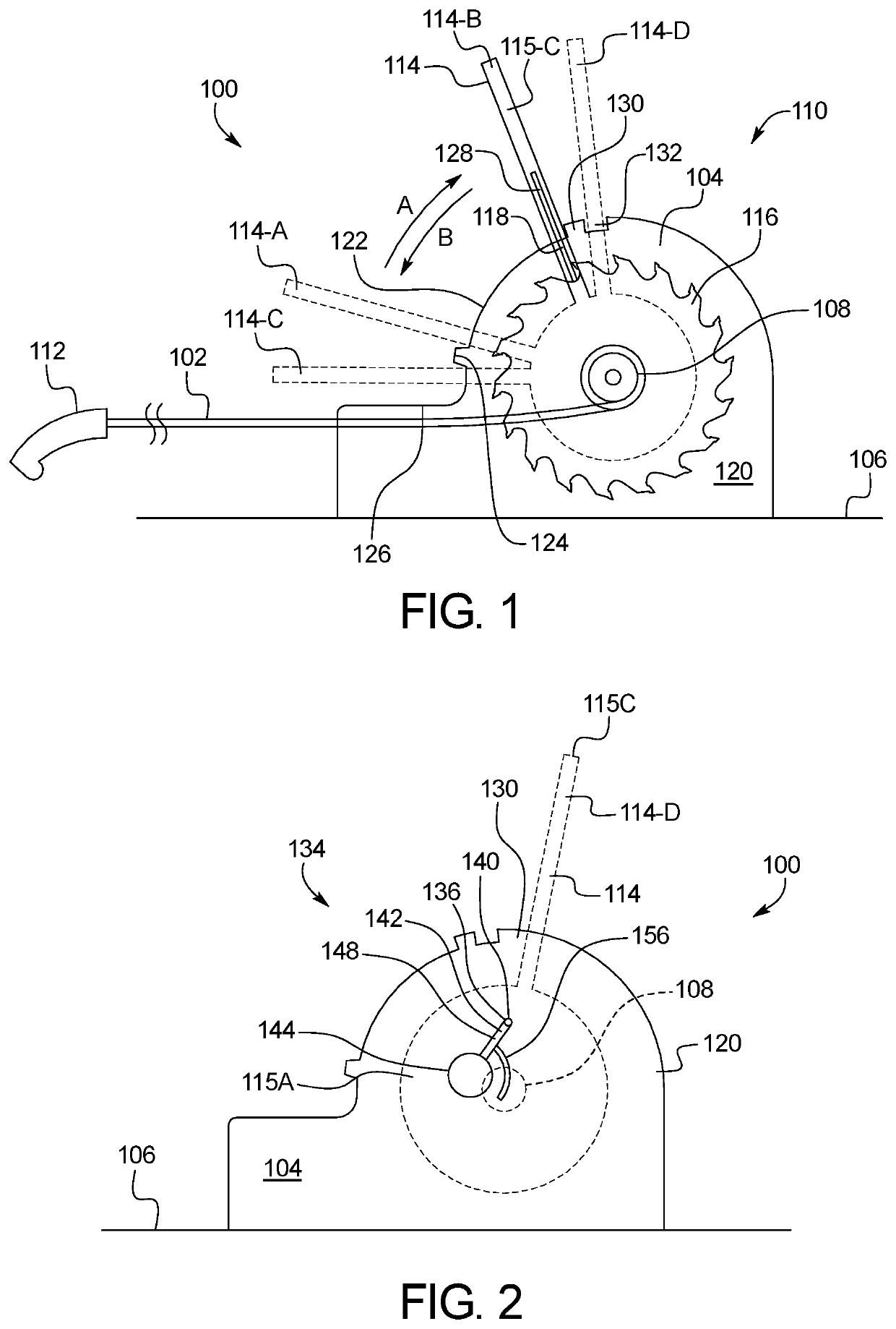
[0027]FIGS. 1-4 illustrate a tie down locking device 100. In this embodiment, the tie down lockout device 100 includes a ratchet strap 102 having a ratchet body 104 that attaches to the platform 106 onto which the boat is loaded. The ratchet strap 102 is wound about a ratchet axle 108 within a rachet assembly 110, and an attachment mechanism 112 on the end of the ratchet strap 102 is secured to the transom on the boat. A locking mechanism 134 (FIG. 2) is incorporated into the ratchet assembly 110 as described in greater detail blow.

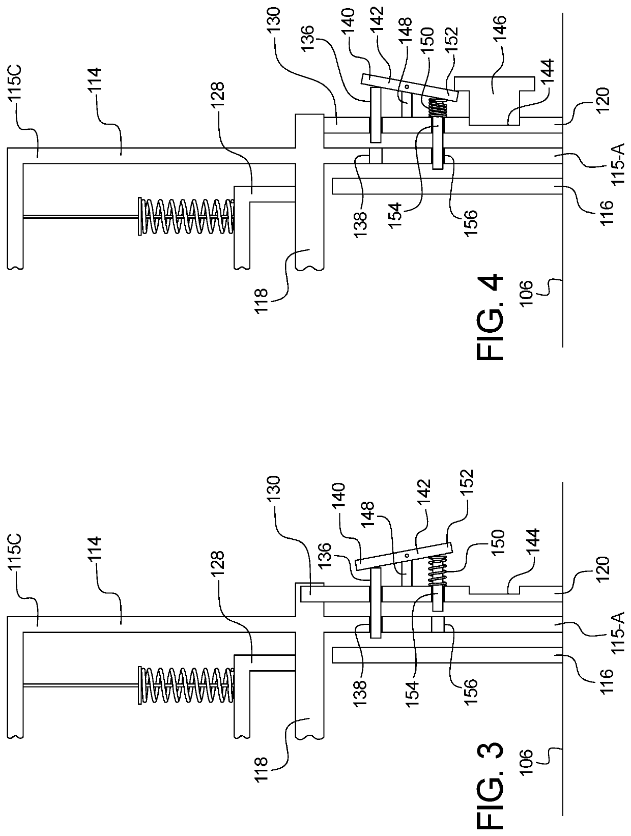
[0028]Referring to FIG. 1, the ratchet assembly 110 includes a ratchet handle 114 that is attached to the ratchet axle 108. The ratchet axle 108 is transversely mounted and rotatably supported within the ratchet body 104, and a pair of ratchet gears 116 are mounted to the ratchet axle 108. The ratchet axle 108 can be rotated by actuating the ratchet handle 114 in directions A and B. At the base of each side of the ratchet handle 114, first and second plan...

second embodiment

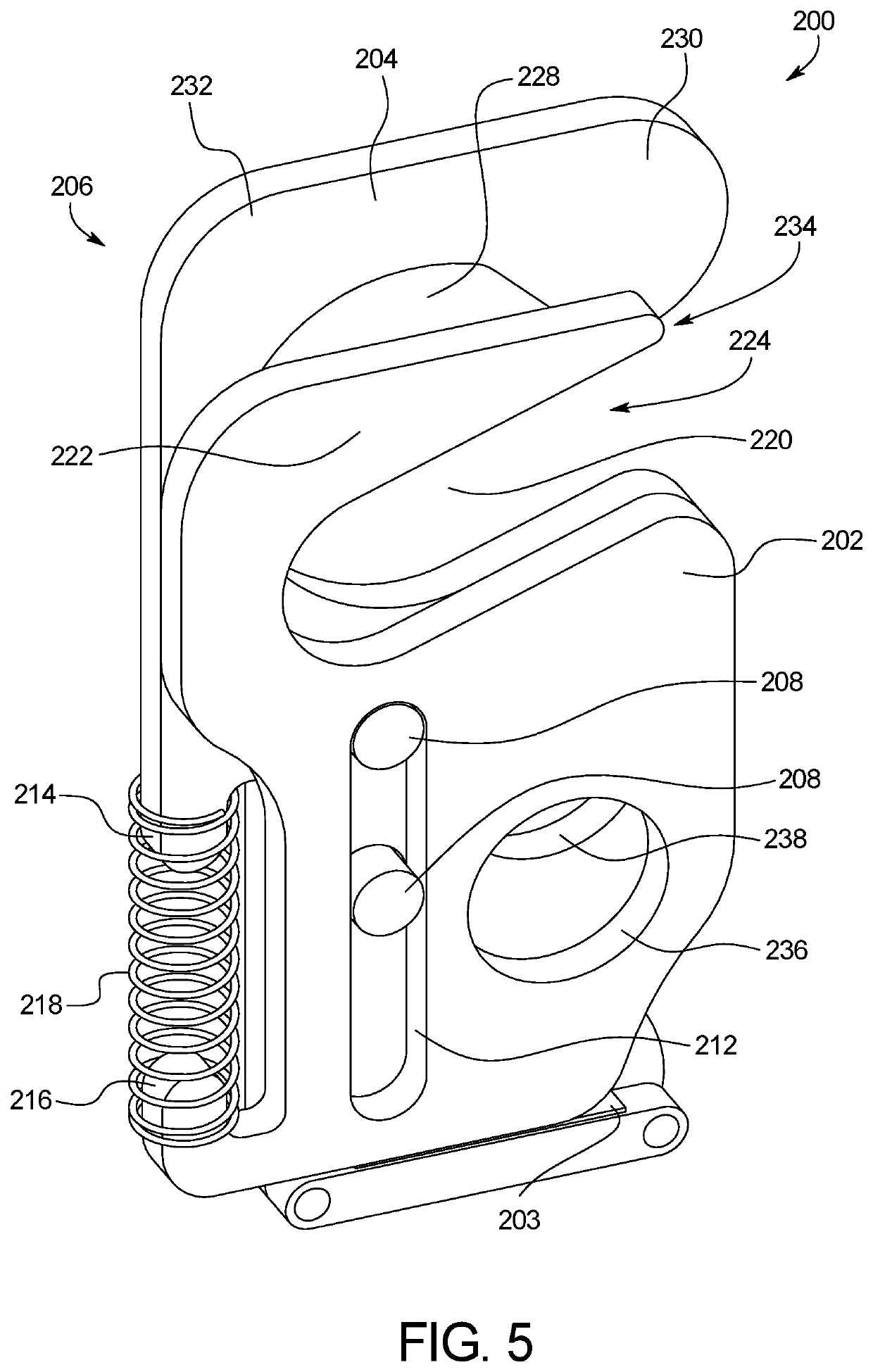
[0040]FIGS. 5 and 6 illustrate a tie down locking device 200. In this embodiment, the tie down lockout device 200 includes front and rear plates 202, 204 that cooperate together to move between an open position shown in FIG. 5 and a closed position shown in FIG. 6. The locking device 200 is attached to a strap 203, which is also secured to a trailer or other platform. During use the locking device 200 connects to the transom of a boat and the strap is pulled taut. The strap 203 may be secured to the tie down locking device 200 through a buckle or any type of securement means.

[0041]The plates 202, 204 are secured together using a pair of bolts, rivets, or other attachment mechanisms 208 positioned within a pair of openings 210 in the rear plate 204 and a longitudinal groove 212 in the front plate 202. The bolts 208 remain stationary on the rear plate 204 while the front plate 202 moves within the constraints of the groove 212. The front and rear plates 202, 204 also include spring pr...


PUM


Abstract

A tie down locking mechanism includes a first plate including a first cavity and a first aperture, a second plate including a second cavity and a second aperture, and a spring mechanism that biases the first and second plates into a first position and that moves the first and second plates into a second position when the bias is overcome with an application of force. Each cavity includes an interior portion connected to an opening on a perimeter of the respective plate. When the first and second plates are in the first position, the openings of the first and second cavities are aligned and the apertures are not aligned. When the first and second plates are in the second position, the openings of the first and second cavities are not aligned and the apertures are aligned.

Description

CROSS-REFERENCE TO RELATED APPLICATIONS[0001]This application is a continuation application of U.S. patent application Ser. No. 16 / 996,542 filed Aug. 18, 2020, the entirety of which is incorporated herein by reference.BACKGROUND OF THE INVENTION[0002]The present subject matter relates generally to tie down locking devices that ensure that the drain plug is either inserted or removed from a boat as needed. More specifically, the present invention relates to tie down locking devices that include a locking mechanism requiring a drain plug to operate.[0003]While the structure and design of the drain and drain plug on a boat is simple, these components serve an important purpose in the functioning of a boat. After the user has finished boating and removes the boat from the water, any water that has entered the hull is drained by lifting the bow of the boat and angling the boat downwards toward the stern with the drain plug removed. This angling positions the drain at the lowermost point....

Claims


Application Information

Patent Timeline
IPC IPC(8): B60P7/08
CPCB60P7/083B60P3/1066
Inventor DEPLARIS, NICHOLAS
Owner DEPLARIS NICHOLAS
Why Eureka
Try Eureka