Microstrip antenna having slot structure

a microstrip antenna and slot technology, applied in the direction of individual energised antenna arrays, resonant antennas, antenna earthings, etc., can solve the problems of insufficient bandwidth of conventional microstrip antennas to meet the requirements of uwb, and shrink the size of microstrips further, so as to achieve sufficient bandwidth, reduce fabrication costs, and reduce the effect of antenna siz

Inactive Publication Date: 2005-11-17
ARCADYAN
View PDF4 Cites 22 Cited by
  • Summary
  • Abstract
  • Description
  • Claims
  • Application Information

AI Technical Summary

Benefits of technology

[0012] Hence, with the use of the present invention, the antenna size can be greatly reduced and the fabricati...

Problems solved by technology

Therefore, it is an important issue about how to further shrink the size of the microstrip patch antenn...

Method used


Image

  • Microstrip antenna having slot structure
  • Microstrip antenna having slot structure
  • Microstrip antenna having slot structure

Examples


Embodiment Construction

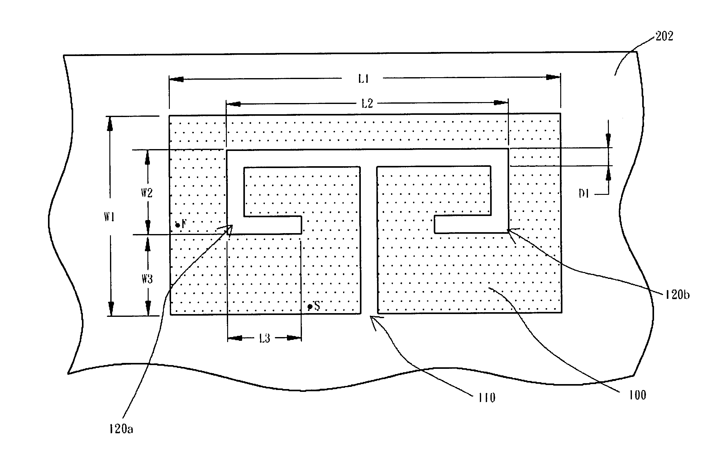
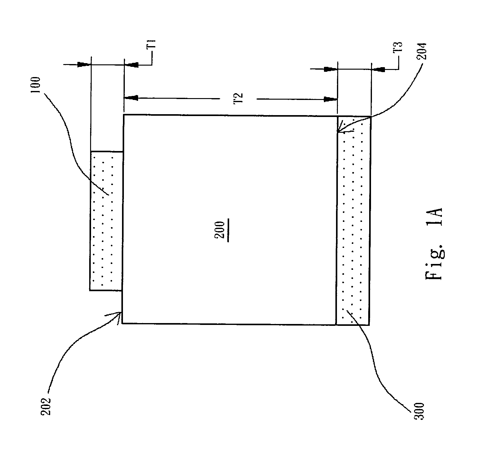
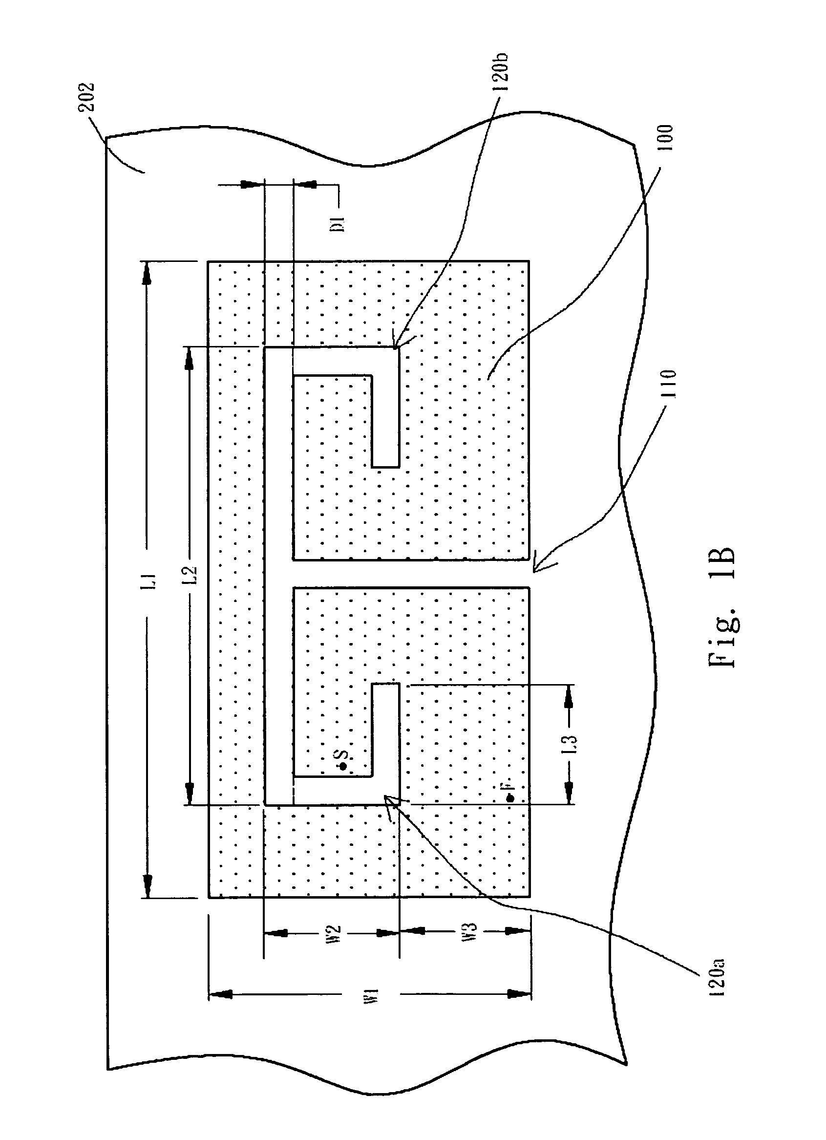
[0025] Referring to FIG. 1A and FIG. 1B, FIG. 1A and FIG. 1B are respective schematic side and top views of a microstrip antenna having a slot structure according to a first preferred embodiment of the present invention. Such as shown in FIG. 1A, a base board 200 (for example: a printed circuit board) has a first surface 202 and a second surface 204, and the first surface 202 is parallel to the second surface 204. A microstrip patch radiator 100 (for example: a rectangle) is formed on the first surface 202 of the base board 200, and ground plane 300 is formed on the second surface 204 of the base board 200, wherein the ground plane 300 may cover part or all of the second surface 204. The base board 200 can be a printed circuit board made of glass fiber material (such as FR4) or other materials, and the microstrip patch radiator 100 and the ground plane 300 are made of metal material.

[0026] Such as shown in FIG. 1B, the microstrip patch radiator 100 has a slot structure (not labeled...


PUM


Abstract

A microstrip antenna having a slot structure is disclosed for providing a sufficient bandwidth so as to meet the antenna requirements. The microstrip antenna is composed of a base board (such as a printed circuit board) and a microstrip patch radiator having the slot structure, wherein the microstrip patch radiator is formed on the base board. The slot structure is composed of a T-shaped slot, an L-shaped slot and a reversed-L-shaped slot, wherein the L-shaped slot and the reversed-L-shaped slot are mirror-reflected to each other.

Description

RELATED APPLICATIONS [0001] The present application is based on, and claims priority from, Taiwan Application Serial Number 93113361, filed May 12, 2004, the disclosure of which is hereby incorporated by reference herein in its entirety. FIELD OF THE INVENTION [0002] The present invention relates to a microstrip antenna having a slot structure, and more particularly, to the microstrip antenna providing a sufficient bandwidth with a symmetrical slot structure. BACKGROUND OF THE INVENTION [0003] With the advancement of communication technologies, various communication products and technologies have been continuously appearing in the market. Moreover, with integrated circuit (IC) technologies getting matured, the size of product has been gradually developed toward smallness, thinness, shortness and lightness. With respect to an antenna used for radiating or receiving signals in the communication products, the size of the antenna determines if the objective of smallness, thinness, short...

Claims


Application Information

Patent Timeline
IPC IPC(8): H01Q1/24H01Q1/38H01Q5/00H01Q9/04H01Q21/20
CPCH01Q1/243H01Q9/0442H01Q9/0421
Inventor LIU, I-RULU, CHIN-HUA
Owner ARCADYAN
Why Eureka
Try Eureka