Applicator head, applicator nozzle arrangement, adaptor plate and mounting plate

Inactive Publication Date: 2005-12-15
NORDSON CORP
View PDF9 Cites 23 Cited by
  • Summary
  • Abstract
  • Description
  • Claims
  • Application Information

AI Technical Summary

Benefits of technology

[0007] An advantage of the invention is that no tool is necessary for replacing the applicator nozzle arrangement. This permits the applicator nozzle arrangement to be quickly and inexpensively changed. A further advantage is that, in the event of a change of the applicator nozzle arrangement, it can be very easily and very precisely positioned. Because precise positioning is an important prerequisite for trouble-free operation of adhesive applicator apparatuses, the invention also reduces the error probability of such installations and thus enhances the availability thereof. Those advantages are achieved by the lever according to the invention.
[0008] By virtue of the fact that it is possible to forego the use of tools for replacing the applicator nozzle arrangement, there is also no longer any need, in terms of the design structure, to take account of the fact that sufficient space is kept free for the use of a tool. In this respect, the specified advantages can be achieved by means of a simple and thus inexpensive structure. In addition, existing applicator apparatuses can be easily retrofitted therewith.
[0009] In a preferred embodiment of the invention the lever is mounted on the housing, or main body. In an installation for applying fluids to a movable substrate, a large number of various applicator nozzle arrangements per applicator head are usually kept on hand. The provision of the lever on the main body minimizes the number of levers required overall.
[0010] It is preferable for the lever to be adapted to exert a force on the applicator nozzle arrangement, in which respect the force acts substantially parallel to the

Problems solved by technology

In order to maintain, repair or replace the applicator head and/or the applicator nozzle arrangement in the state of the art, it is necessary to release the large number of fixing screws which connect the applicator nozzle arrangement to the applicator head, such screws generally being difficult to access by virtue of the geometry of the

Method used


Image

  • Applicator head, applicator nozzle arrangement, adaptor plate and mounting plate
  • Applicator head, applicator nozzle arrangement, adaptor plate and mounting plate
  • Applicator head, applicator nozzle arrangement, adaptor plate and mounting plate

Examples


Embodiment Construction

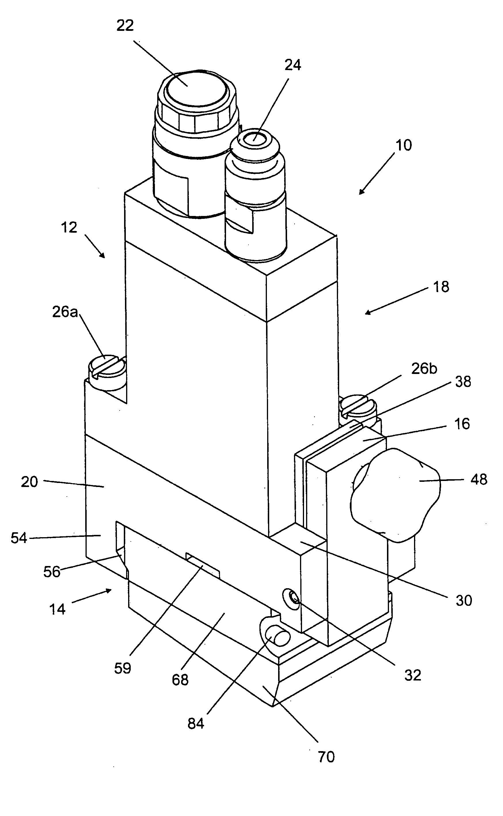
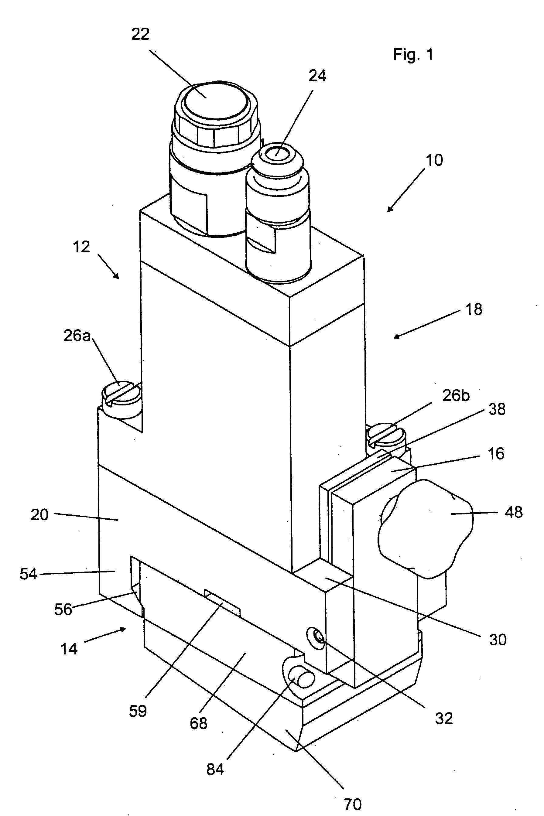
[0034]FIG. 1 shows an applicator head 10, or apparatus 10, which has a main body 12, or housing 12, an associated applicator nozzle arrangement 14 and a lever 16. The main body 12 includes a dosing dispenser 18 and a mounting plate 20.

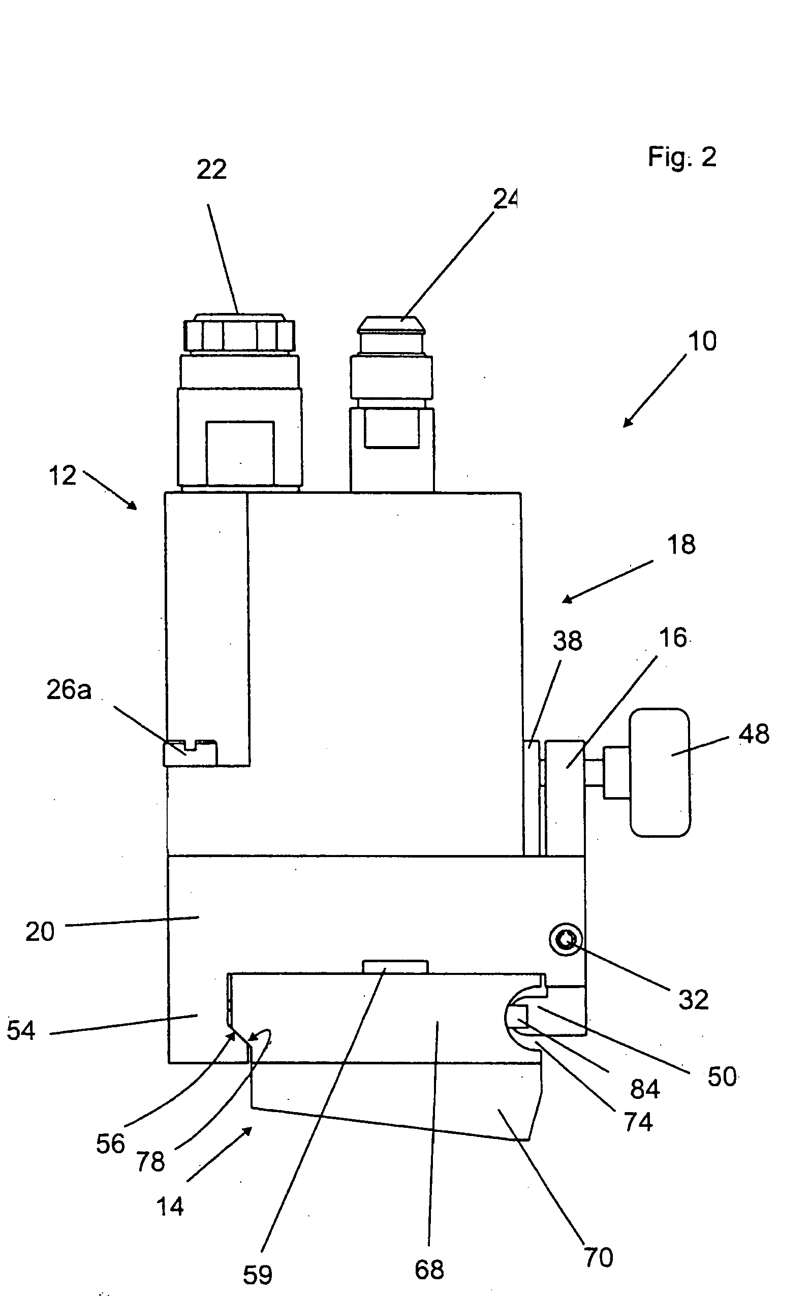
[0035] The dosing dispenser 18 is of substantially cuboidal configuration and at one of its narrow sides has an electrical connection 22 for connection to a voltage source and a connection 24 for the feed of fluid. A solenoid (not shown here) which enables or interrupts the delivery of fluid from the applicator head 10 is supplied with power by way of the connection 22. The mounting plate 20 is mounted to the side opposite to the connections 22, 24, by two screws 26a, 26b. In that case the screw 26a engages into a screwthreaded hole 28a (see FIG. 6) and the screw 26b correspondingly engages into a screwthreaded hole 28b in the mounting plate 20. The dosing dispenser 18 and the mounting plate 20 are flush with each other at three sides.

[0036] The moun...


PUM


Abstract

An apparatus for applying fluid from a fluid source to a substrate. The apparatus comprises a housing configured to receive the fluid from the fluid source, a nozzle arrangement in fluid communication with the housing, and a lever pivotally mounted to the housing for releasably securing the nozzle arrangement thereto.

Description

TECHNICAL FIELD [0001] The invention concerns an apparatus for applying fluid comprising housing and an associated applicator nozzle arrangement releasably secured thereto. BACKGROUND [0002] Apparatuses which include applicator heads, applicator nozzle arrangements, adaptor plates and / or mounting plates are used in various sectors of industry in order to continuously or intermittently apply different materials which are capable of flow. For example, adhesives, lacquers, and coating materials are applied to hygiene articles, wood products, machine parts, and bodywork parts of vehicles or the like, in bead form, line form, point form or over an area. [0003] For that purpose the applicator nozzle arrangements and applicator heads are connected to a fluid source, for example, an adhesive container, from which the fluid may be conveyed by a pump through a feed passage to the applicator nozzle arrangement. The flow of fluid can be interrupted or enabled, such as by a valve arrangement whi...

Claims


Application Information

Patent Timeline
IPC IPC(8): B05B15/06B05C5/02
CPCB05B15/65B05C5/02
Inventor DE LEEUW, VICTORVAN DER HEIJDEN, WENDELINUS CORNELIS
Owner NORDSON CORP
Why Eureka
Try Eureka