
Multiple-field based code generator and decoder for communications systems

Inactive Publication Date: 2007-08-23
QUALCOMM INC
View PDF105 Cites 133 Cited by
  • Summary
  • Abstract
  • Description
  • Claims
  • Application Information

AI Technical Summary

Benefits of technology

[0031]Numerous benefits are achieved by way of the present invention. For example, in a specific embodiment, the computational expense of encoding data for transmission over a channel is reduced. In another specific embodiment, the computational expense of decoding such data is reduced. In yet another specific embodiment, the error probability of the decoder is reduced, while keeping the computational expense of encoding and decoding low. Depending upon the embodiment, one or more of these benefits may be achieved. These and other benefits are provided in more detail throughout the present specification and more particularly below.

Problems solved by technology

Lost data (erasures) are often easier to deal with than corrupted data (errors) because the recipient cannot always tell when corrupted data is data received in error.
The problem of data transmission becomes more difficult when the channel is in an adverse environment or the transmitter and / or receiver has limited capability.
Often, however, a reverse channel is not available or feasible or is available only with limited capacity.
For example, where the transmitter is transmitting to a large number of receivers, the transmitter might not be able to handle reverse channels from all those receivers.
As a result, communication protocols often need to be designed without a reverse channel or with a limited capacity reverse channel and, as such, the transmitter may have to deal with widely varying channel conditions without a full view of those channel conditions.
The problem of data transmission between transmitters and receivers is made more difficult when the receivers need to be low-power, small devices that might be portable or mobile and need to receive data at high bandwidths.
Packet loss often occurs because sporadic congestion causes the buffering mechanism in a router to reach its capacity, forcing it to drop incoming packets.
Symbols are often corrupted by sporadic noise, periodic noise, interference, weak signal, blockages in the channel, and a variety of other causes.
Chain reaction codes have many uses, including the generation of an arbitrary number of output symbols in an information additive way, as opposed to an information duplicative way, wherein the latter is where output symbols received by a receiver before being able to recover the input symbols duplicate already received information and thus do not provide useful information for recovering the input symbols.
On the other hand, these FEC codes are typically much less efficient in terms of encoding and decoding complexity, and one of the primary reasons for that is because the operations over larger fields are much more complex and / or are not natively supported on modern CPUs, and the complexity typically grows as the field size grows.
Thus, the FEC codes that operate over larger finite fields are often much slower or impractical compared to FEC codes that operate over GF(2).

Method used


Image

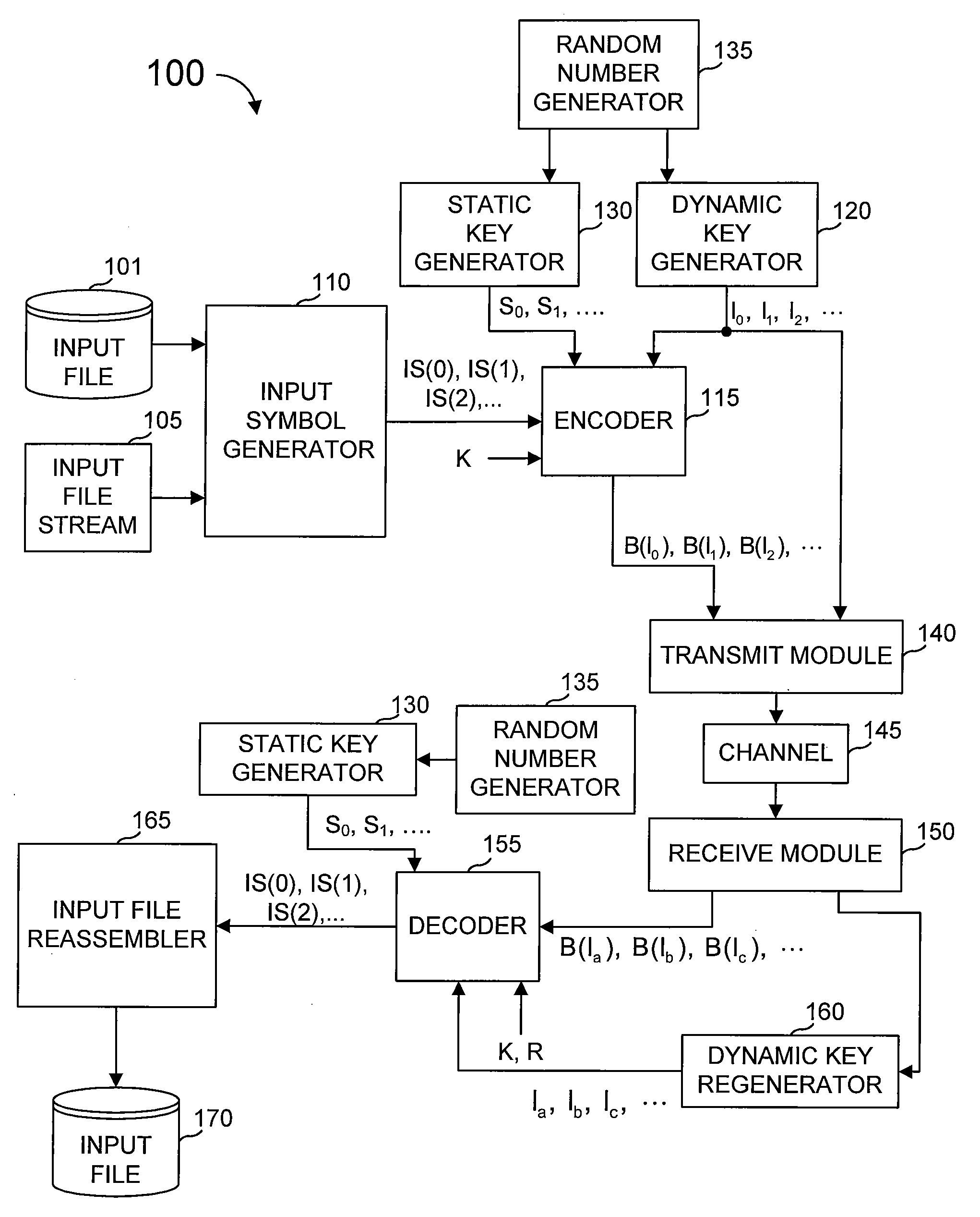
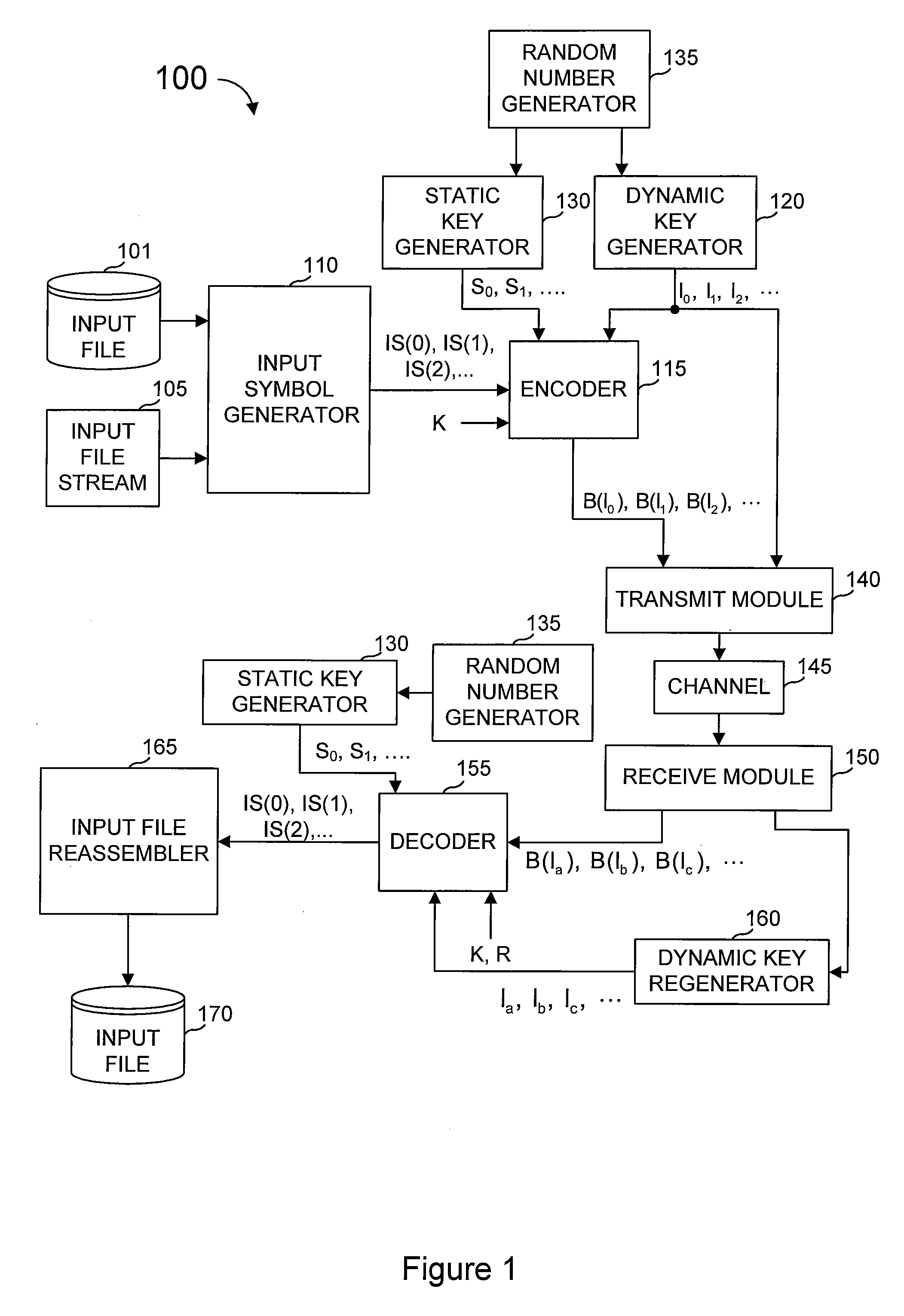
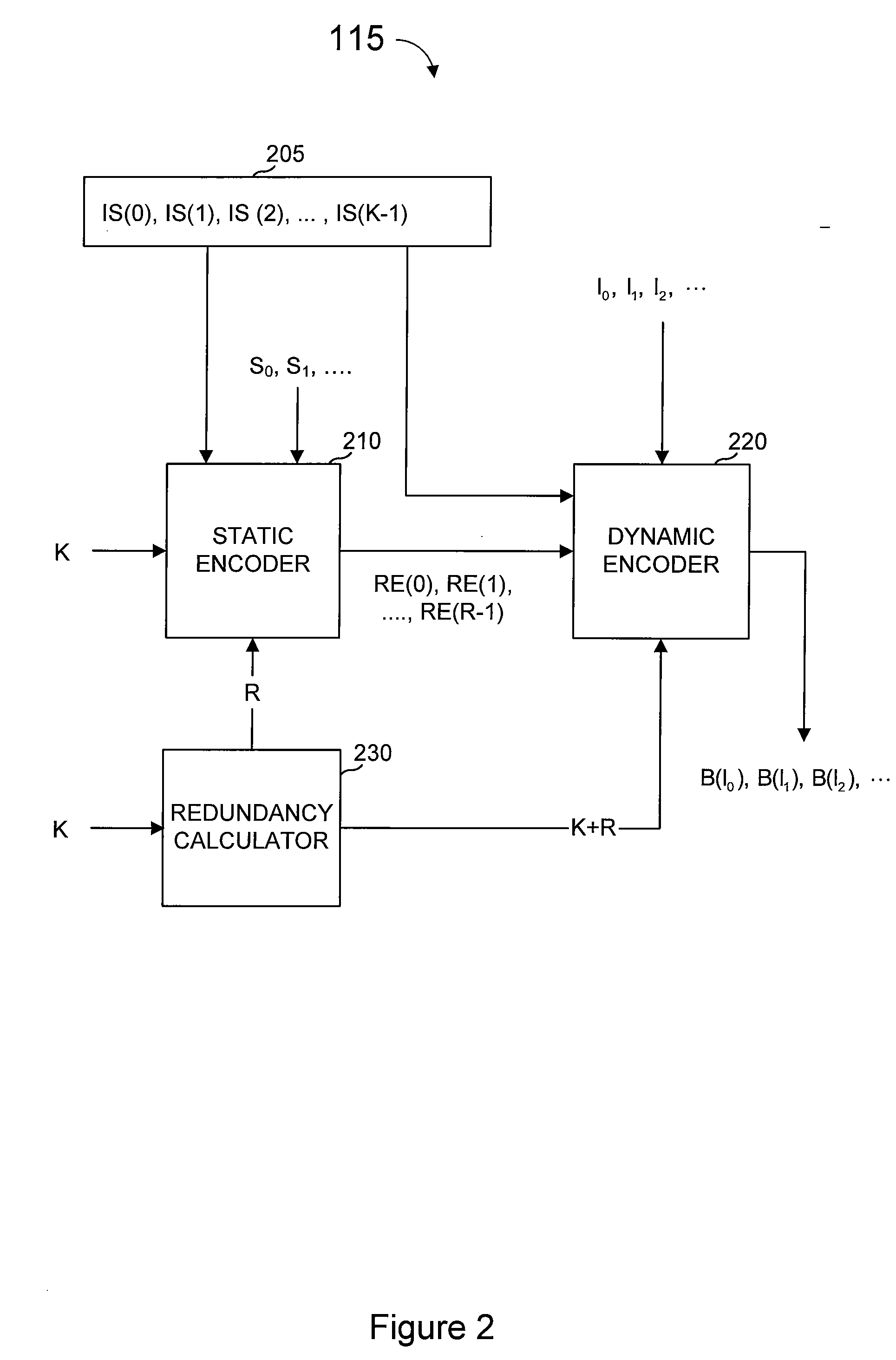
  • Multiple-field based code generator and decoder for communications systems
  • Multiple-field based code generator and decoder for communications systems
  • Multiple-field based code generator and decoder for communications systems

Examples


Embodiment Construction

[0067]The inventions described herein make use of mathematical operations for encoding and decoding based on operations in one or more finite fields. Finite fields are finite algebraic structures for which the four arithmetic operations are defined, and which form a field with respect to these operations. Their theory and their construction are well understood by those of skill in the art.

[0068]In the description that follows we shall require a multiplication process to be defined between the elements of a finite field and symbols which represent or are derived from the data to be encoded or decoded. Three distinct types of symbols are considered in this description: input symbols comprise information known to the sender which is to be communicated to the receiver, redundant symbols comprise symbols which are derived from the input symbols and output symbols comprise symbols which are transmitted by the sender to the receiver. Of the many possibilities for defining such a multiplica...


PUM


Abstract

A method of encoding data for transmission from a source to a destination over a communications channel is provided. The method operates on an ordered set of input symbols and includes generating a plurality of redundant symbols from the input symbols based on linear constraints. The method also includes generating a plurality of output symbols from a combined set of symbols including the input symbols and the redundant symbols based on linear combinations, wherein at least one of the linear constraints or combinations is over a first finite field and at least one other of the linear constraints or combinations is over a different second finite field, and such that the ordered set of input symbols can be regenerated to a desired degree of accuracy from any predetermined number of the output symbols.

Description

CROSS-REFERENCES[0001]This application claims priority from and is a non-provisional of U.S. Provisional Patent Application No. 60 / 775,528 filed Feb. 21, 2006.[0002]The following references are include here and are incorporated by reference for all purposes:[0003]U.S. Pat. No. 6,307,487 entitled “Information Additive Code Generator and Decoder for Communication Systems” issued to Luby (hereinafter “Luby I”);[0004]U.S. Pat. No. 6,320,520 issued to Luby et al. entitled “Information Additive Group Code Generator and Decoder for Communication Systems” (hereinafter “Luby II”);[0005]U.S. Pat. No. 7,068,729 issued to Shokrollahi et al. entitled “Multi-Stage Code Generator and Decoder for Communication Systems” (hereinafter “Shokrollahi I”);[0006]U.S. Pat. No. 6,909,383 entitled “Systematic Encoding and Decoding of Chain Reaction Codes” issued to Shokrollahi et al. (hereinafter “Shokrollahi II”);[0007]U.S. Pat. No. 6,856,263 entitled “Systems and Processes for Decoding Chain Reaction Codes ...

Claims


Application Information

Patent Timeline
IPC IPC(8): H04B14/04
CPCH04L1/0041H04L1/0045H04L1/0057H03M13/19H03M13/3761H03M13/1102H04L1/0065H03M13/00
Inventor SHOKROLLAHI, M. AMINLUBY, MICHAEL G.WATSON, MARKMINDER, LORENZ
Owner QUALCOMM INC
Learn More