
Vehicle suspension system
a suspension system and vehicle technology, applied in the direction of elastic bearings, machine supports, rigid support of bearings, etc., to achieve the effect of reducing the torque on the axle, reducing the distance between the axle and the dock, and high roll stability
- Summary
- Abstract
- Description
- Claims
- Application Information
AI Technical Summary
Benefits of technology
Problems solved by technology
Method used
Image

Examples
Embodiment Construction
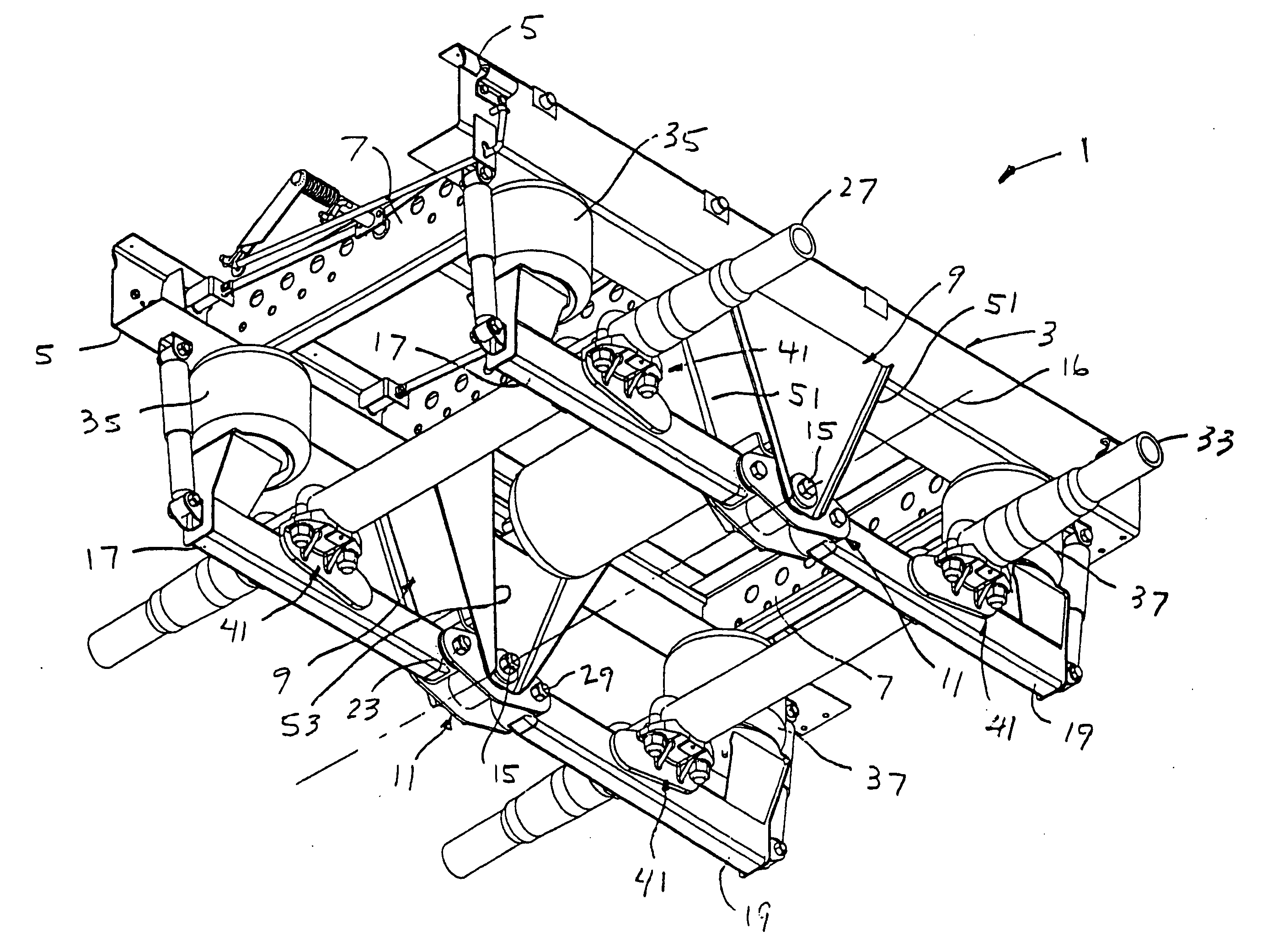
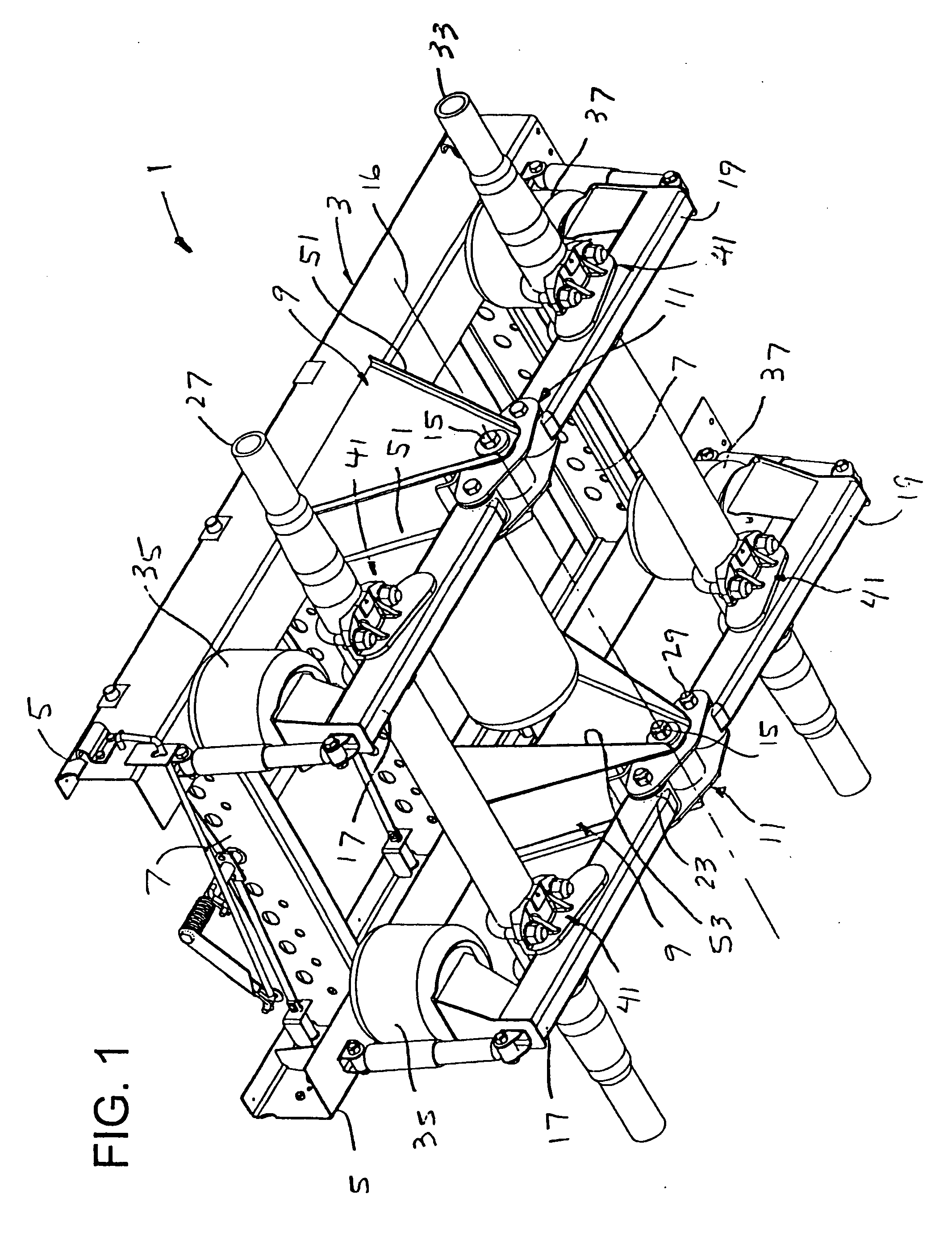
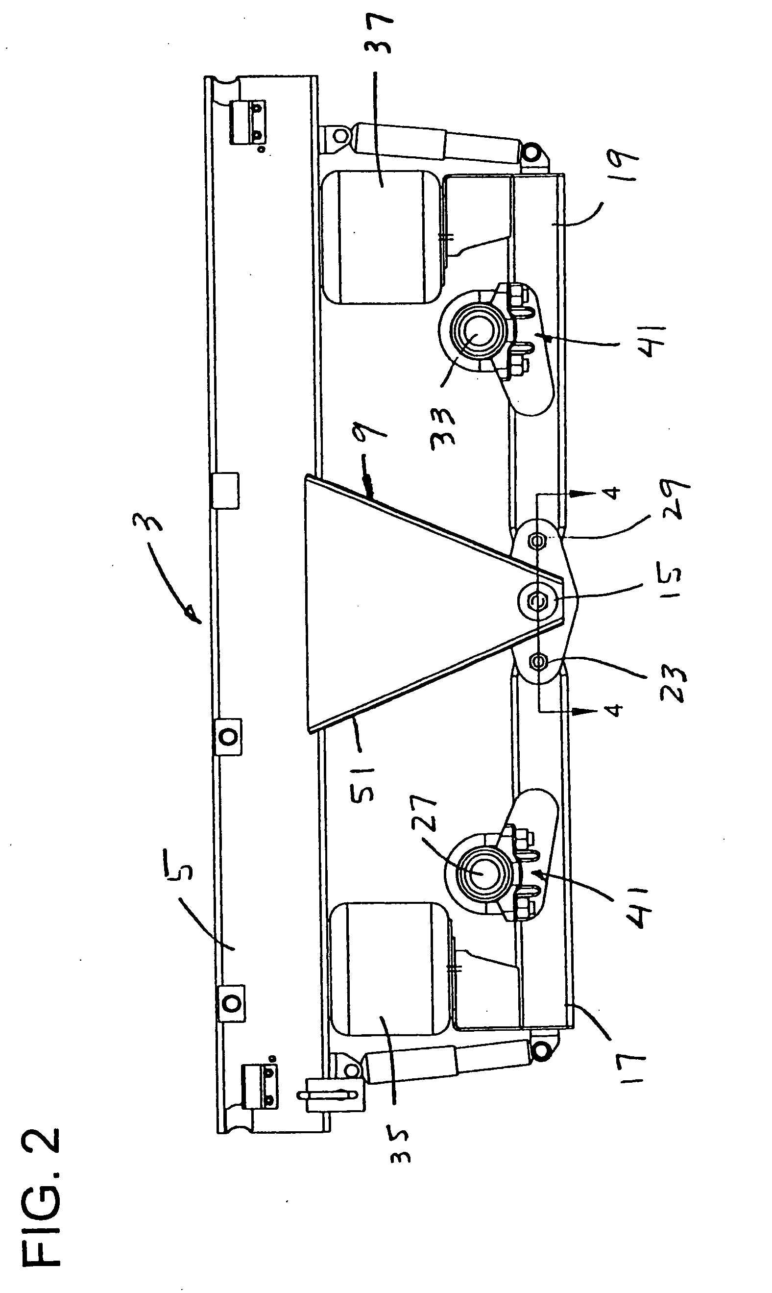
[0055] Referring now to FIGS. 1-4 of the drawings, a vehicle suspension of the present invention is designated in its entirety the reference numeral 1. As shown, the suspension is a slider of the type which is affixed to the frame of truck. However, it will be understood that the present invention has applications to vehicle suspensions generally.
[0056] The suspension comprises a frame 3 which includes a pair of parallel rails 5 connected by cross members 7, and hangers 9 depending from the rails 5 at opposite sides of the frame generally midway between the ends of the rails. The frame has forward and rearward ends, the forward end being the left end as viewed in FIG. 1 and the rearward end being the opposite (right) end. In accordance with one aspect of the present invention, the frame further comprises a pair of levers 11, referred to as equalizers, one at one side of the frame 3 and the other at the other side of the frame. Each lever 11 (comprising two parallel bars 11a, 11bin ...
PUM
 Abstract
Description
Claims
Application Information