Archery laser arrow

Inactive Publication Date: 2005-12-22
NOCKOUT OUTDOORS LLC
View PDF16 Cites 23 Cited by
  • Summary
  • Abstract
  • Description
  • Claims
  • Application Information

AI Technical Summary

Benefits of technology

[0006] The laser targeting system of the present invention eliminates the problem of parallax, that is, which is the angle between the arrow's path and the archer's line of sight. A novel solution as in the present invention is accomplished by having a laser integrated into the arrow or arrowhead such that the beam is projected down the axis of the arrow. Still another novel solution is to have an arrow rest with an integrated laser. By having the laser extend the axis of the arrow to the target, the laser spot produced on the target accurately represents where the arrow will hit once released, and eliminates the parallax angle between the archer's line of sight and the arrow's path. This behavior occurs in the flat-trajectory range of any given bow, rest, and arrow setup. The flat-trajectory range is typically 20 to 30 yards depending on the age and technology of the

Problems solved by technology

Lasers have been used on archery equipment for aiming, but they all suffer from the problem of parallax.
Currently, there are no functional lasers that are mounted on or near to the arrow, such as arrows, arrowheads, or arrow rests with integrated lasers.
Additionally, there are no sights that allow for the enhan

Method used


Image

  • Archery laser arrow
  • Archery laser arrow
  • Archery laser arrow

Examples


Embodiment Construction

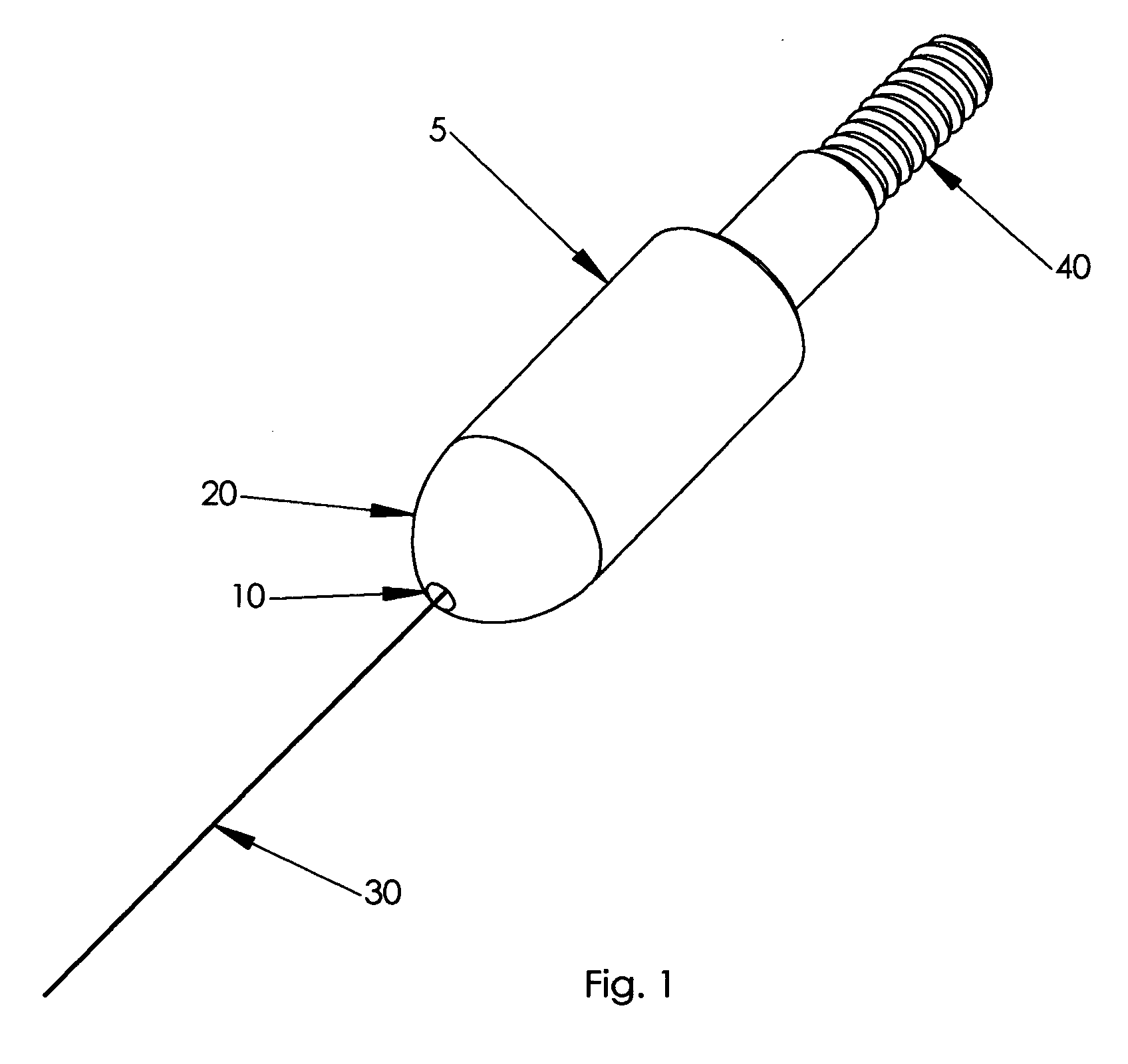
[0016] Referring to FIG. 1, an arrowhead comprises an elongated body (5) having an aperture (10) at a first end (20) through which a laser beam (30) projects. The arrowhead also comprises a threaded end (40) for attaching to different arrows. The laser is integrated into the arrowhead such that the laser beam projects through the aperture in a parallel and substantially coaxial relationship with the arrow. The aperture may comprise a glass window or some other transparent media that allows the laser beam to emanate unobstructed from the arrowhead.

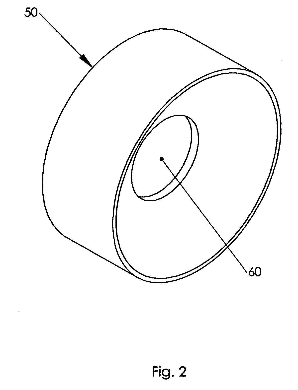
[0017] Referring to FIG. 2, a sight (50) fabricated with an optical filter in the aperture (60) visually enhances the laser spot produced on the target. The current embodiment consists of a laser having a wavelength of 650 nm and thus a corresponding sight consisting of a filter that blocks most of the other visible wavelengths except those around 650 nm. The sight filter is designed to pass the wavelength of the laser. Other wavelength la...


PUM


Abstract

The laser targeting system of the present invention eliminates the problem of parallax between the arrow's path and the archer's line of sight. An embodiment is a laser integrated into an arrow such that the beam is projected down the axis of the arrow. Another embodiment is an arrow rest with an integrated laser, which can have an angular adjustment. By having the laser extend the axis of the arrow to the target, the laser spot produced on the target accurately represents where the arrow will hit once released, and eliminates the parallax angle between the archer's line of sight and the arrow's path. The present invention also provides a means for using a single laser beam to project a diffractive pattern onto a target, such as several spots or crosshairs. For advanced visibility of the laser spot, an optical filter or infrared vision optical sensors can be used.

Description

BACKGROUND OF THE INVENTION [0001] 1. Field Of The Invention [0002] The present invention relates to archery equipment, particularly to the method and apparatus for aiming with lasers and enhanced laser sighting with optical filters and imaging devices. [0003] 2. Description Of The Related Art [0004] Lasers have been used on archery equipment for aiming, but they all suffer from the problem of parallax. Currently, there are no functional lasers that are mounted on or near to the arrow, such as arrows, arrowheads, or arrow rests with integrated lasers. Lasers at visible wavelengths and other parts of the electromagnetic spectrum may be used, such as in the infrared. Additionally, there are no sights that allow for the enhanced visibility of the laser spot by utilizing optical filters or imaging devices. [0005] U.S. Pat. No. 6,134,793, issued on Oct. 24, 2000 to James C. Sauers, describes a laser attached to an arrow used only for alignment of a bow sight and not while aiming, and is ...

Claims


Application Information

Patent Timeline
IPC IPC(8): F41B5/22F41G1/467F42B6/04F42B6/08
CPCF41B5/143F42B6/08F42B6/04F41G1/467
Inventor MINICA, STUARTTABOADA, JOHN MARTIN
Owner NOCKOUT OUTDOORS LLC
Why Eureka
Try Eureka