Broadcast receiver

a receiver and broadcast technology, applied in the field of broadcast receivers, can solve the problems of user irritation, continuous display of images, and inability to meet user's needs, and achieve the effect of preventing user's feeling of uneasiness

Inactive Publication Date: 2006-01-19
FUNAI ELECTRIC CO LTD
View PDF3 Cites 19 Cited by
  • Summary
  • Abstract
  • Description
  • Claims
  • Application Information

AI Technical Summary

Benefits of technology

[0014] As mentioned above, when any one of the channels stored in the memory unit is selected and the receiving state of the broadcasting signal of the television broadcasting in the selected channel is acceptable, it is possible to immediately look and listen the broadcasting in the selected channel in acceptable state. When the receiving state of the signal broadcasted in the selected channel is unacceptable at a time when the channel is selected or when the receiving state becomes unacceptable (worse) at a certain time after the channel is selected, it is possible to automatically receive the broadcasted signal in the selected channel with predetermined goodness, without necessity of manual operation. On the other hand, in the above mentioned case, when the determination of the directivity direction in which the television broadcasting in the selected channel is received with predetermined goodness is impossible and a new channel is selected, the control unit suspends the switching of the directivity direction, reads out the direction information of the selected new channel fro...

Problems solved by technology

Therefore, there is a problem that a time period from a time when the channel is switched to a time when the best image is obtained becomes long and a user may be irritated.
Further, in a case wher...

Method used


Image

  • Broadcast receiver
  • Broadcast receiver
  • Broadcast receiver

Examples


Embodiment Construction

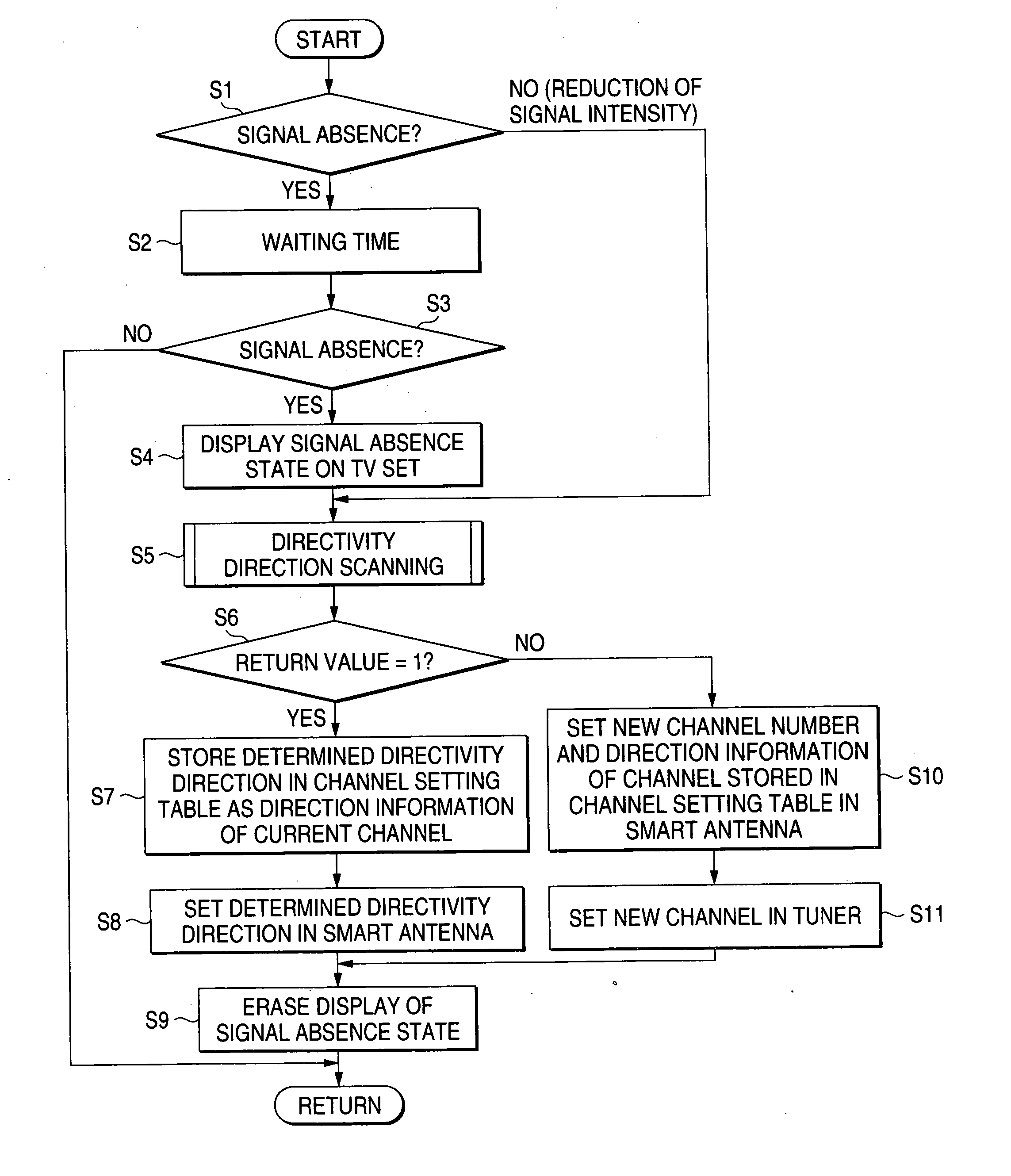
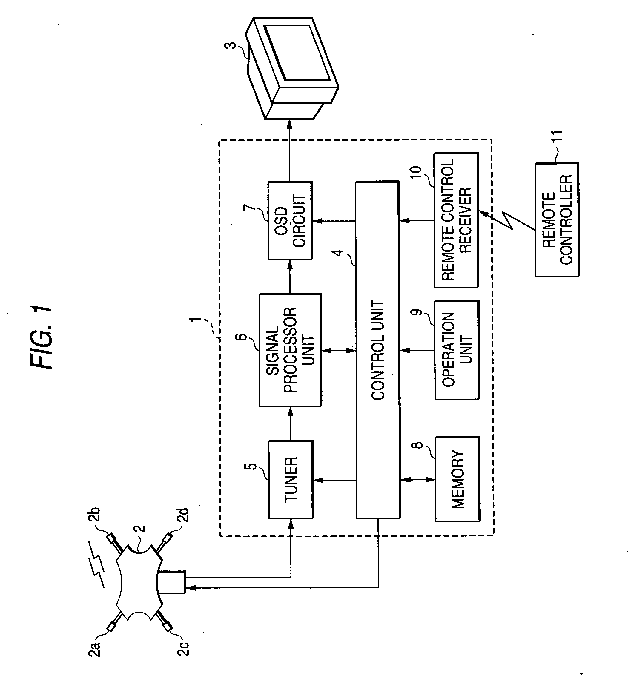
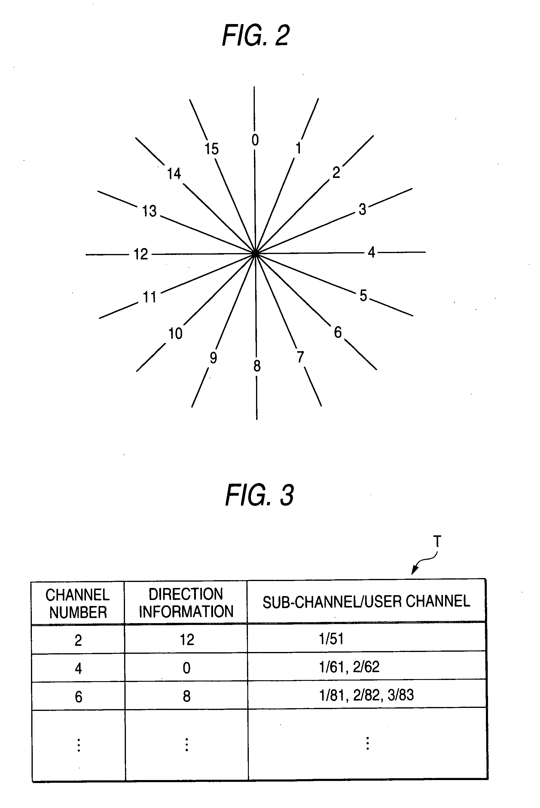
[0022]FIG. 1 is a block circuit diagram showing a receiving system of a television broadcasting (referred to as “TV broadcasting”, hereinafter). A broadcasting receiver 1 and a television receiver (referred to as “TV set”, hereinafter) 3 are located within a house of an ordinary family and connected to each other by a cable. A smart antenna 2 is mounted on a roof of the house, etc., and connected to the broadcast receiver 1 through a cable. The smart antenna 2 is an example of the antenna whose directivity direction can be switched (referred to as “directivity switching antenna”, hereinafter) and, according to the standards, the directivity thereof can be switched between 16 radial directions. Further, the smart antenna 2 is equipped with four (4) antenna elements 2a to 2d, phase shifters provided correspondingly to the respective antenna elements 2a to 2d, a synthesizer and a control circuit, etc., (the other components than the antenna elements 2a to 2d are not shown). The directi...


PUM


Abstract

When a channel of a digital TV broadcasting is selected, a direction information of the channel, which is stored in a channel setting table, is set in a smart antenna and then, in a case of a signal absence state of a broadcasting signal or when a reduction of receiving signal intensity is detected, an optimal directivity direction, in which the broadcasting signal is reproducible and the receiving state of the wave is optimal, is determined by switching (scanning) the directivity direction of the smart antenna. And, the determined directivity direction is stored in the channel setting table as the direction information of a current channel and the directivity direction is set in the smart antenna.

Description

BACKGROUND OF THE INVENTION [0001] 1. Field of the Invention [0002] The present invention relates to a broadcast receiver for receiving a broadcasting of a predetermined channel transmitted from a broadcasting station by using a directivity switching antenna. [0003] 2. Description of the Related Art [0004] In the USA, etc., an individual ordinary home is usually surrounded by a plurality of interspersed broadcasting stations (or base stations). In order to make reception of broadcasts from all of such broadcasting stations possible under such circumstances, it has been proposed to control directivity of an antenna by providing a plurality of antenna elements on the antenna and changing amplitude and phase of radio wave to be received by the antenna elements (for example, JP-A-11-298226 (paragraphs 0008 to 0010)). In JP-A-11-298226, when a channel of a TV receiver is switched to another, the directivity of antenna is scanned omnidirectionally from 0° to 3600 to search a directivity d...

Claims


Application Information

Patent Timeline
IPC IPC(8): H04N7/20H01Q3/24H04B1/16H04B7/08H04B7/10H04N5/44H04N5/445
CPCH04N5/50H04N21/4345H04N21/4882H04N21/44209H04N21/4383
Inventor ONOMATSU, TAKEHIRONARITA, SHUSUKE
Owner FUNAI ELECTRIC CO LTD
Why Eureka
Try Eureka