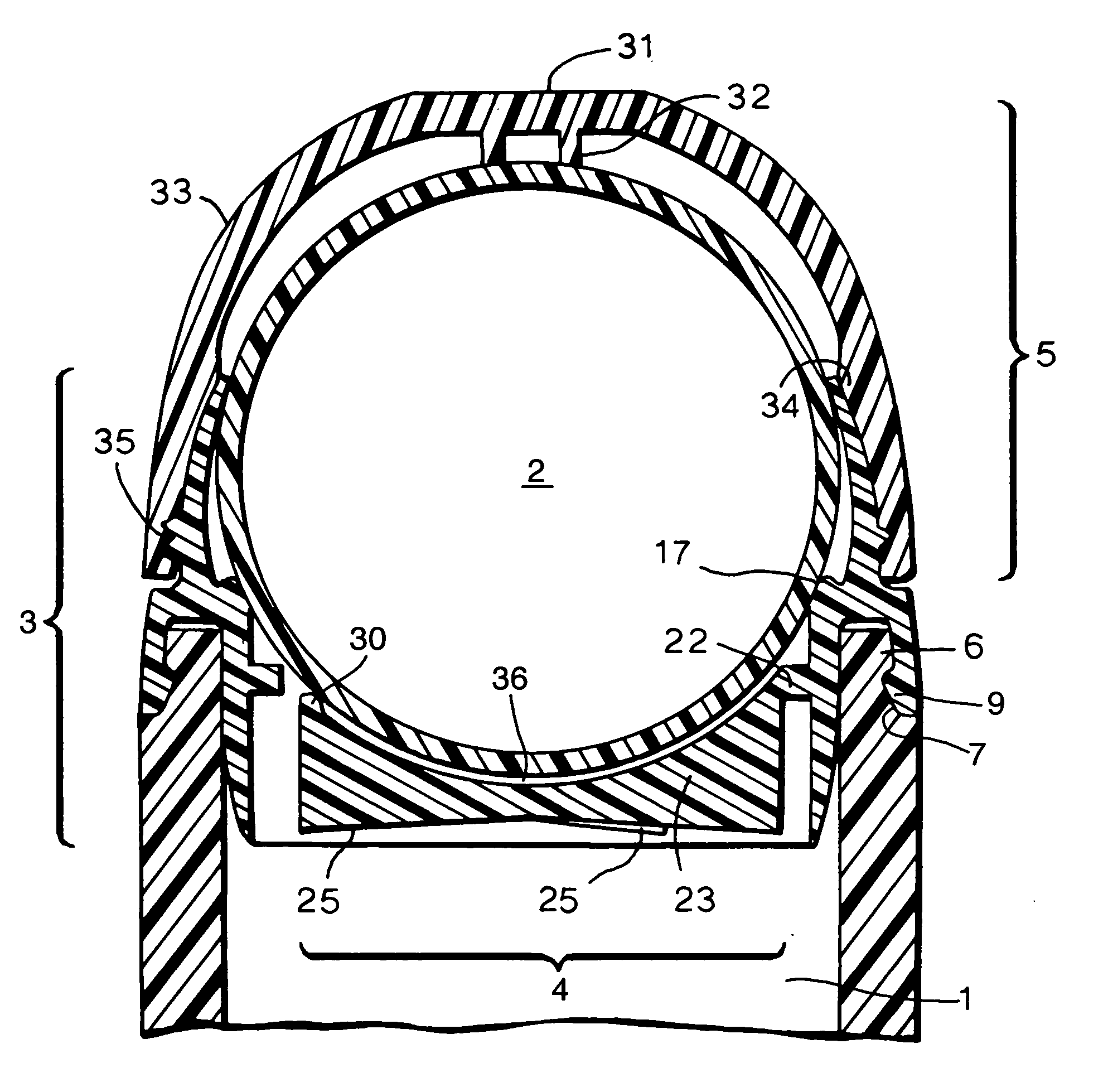
[0014] The present invention is directed to improving the control of the flow of liquid from a roll-on dispenser by modifications to the interior surface of the housing for the roller from its sealing ring through to its outward end, which result in localised disruption of or modification the flow of fluids across that surface in the housing chamber.
[0024] However, it is particularly desirable to employ a spider having a top surface parallel with that of the roller which when the roller is a ball means a convex profile and especially a spider in accordance with the disclosure in a co-pending application of even date entitled “Improvements in a Cosmetic Dispenser”, any supplementary description and accompanying drawings compared with the present text and drawings being incorporated herein by reference. Use of such a particularly desirable spider, that can wipe excess liquid off the ball to leave a film of pre-determined depth, can contribute to the reduction of fluctuations between successive topical applications of the cosmetic formulation.
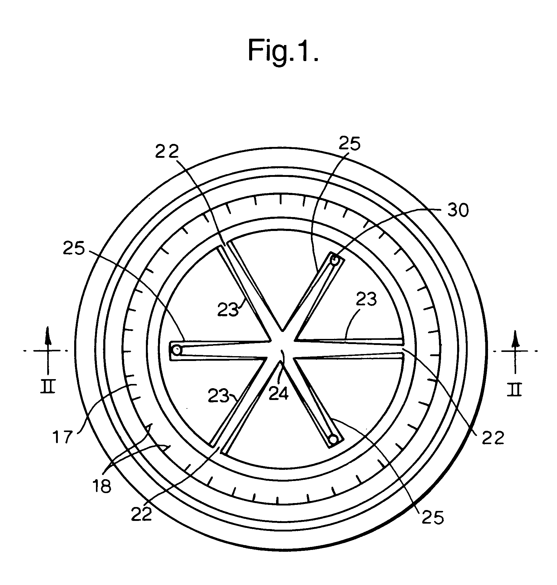
[0027] In many embodiments, the spider comprises a hub from which spokes radiate towards the housing side-wall. If desired, all the spokes can extend between the side-wall and the hub, and for convenience herein these can be called fixed spokes. However, some of the spokes that radiate from the hub and spokes that radiate towards the centre of the housing from the side-wall can have a free end, by which free end is meant that it is not secured to respectively the side-wall or the hub, and for convenience herein these can be called free spokes. It is preferred to employ a mixture of free and fixed spokes, for example in a ratio of from 1:2 to 2:1, and conveniently at 1:1. The free spokes tend to be more flexible whereas the fixed spokes tend to be more rigid and assist in the production of the combined housing and spider, for example in
injection moulding. It is especially desirable for fixed and free spokes to arranged symmetrically, such as 1 or 2 free spokes interposed between adjacent fixed spokes. By adopting a symmetrical arrangement, the ball can be centred more easily, thereby ensuring best that the spokes control the depth of liquid film more evenly. One especially desirable arrangement comprises an even number of spokes in total being 4, 6 or 8 having alternate fixed and free spokes symmetrically arranged around the side-wall.
[0029] The localised contact means desirably comprises a boss or
pimple standing proud of the surface of the spider, specifically proud of the surface of the spokes facing the ball. The boss or
pimple is desirably of round or rounded lateral cross section. The boss or
pimple advantageously has a bevelled or rounded chamfer to its contact edge with the ball, thereby to minimise frictional contact with the ball. The boss or pimple advantageously is hemispherical or a cylinder terminating in a hemisphere. The orthogonal height of the pimple, which controls the depth of the liquid film adhering to the ball, is often, for a hand-held cosmetic dispenser, selected in the range of from 300 to 2000 μm and in many instances from 350 to 750 μm.
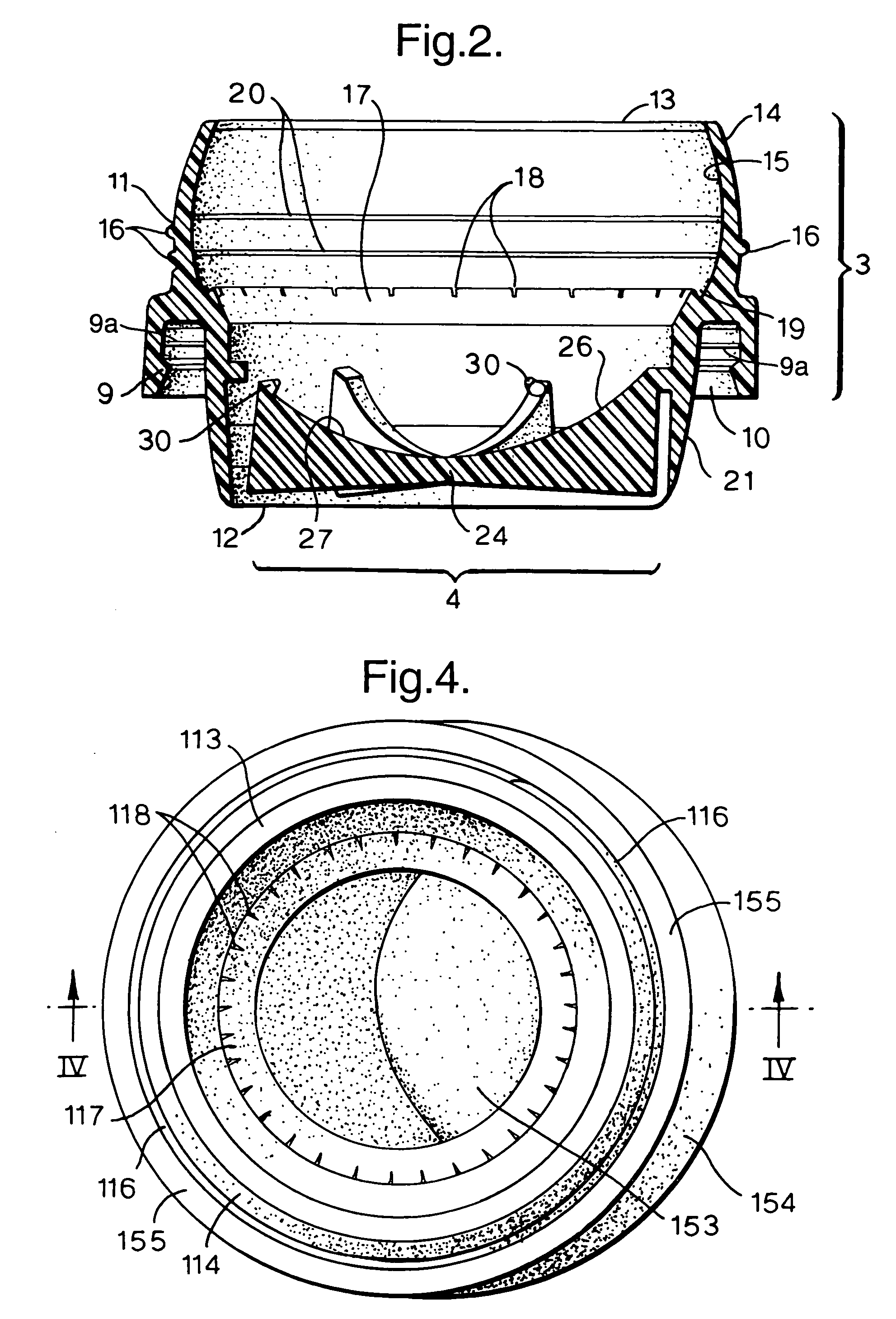
[0035] Advantageously, the spokes of the spider taper slightly from base to tip. This feature enables the sides of the
spoke adjacent to its tip to extend at or close to the radial direction of the ball, for example within about 10 degrees, thereby enabling the tip to encounter the liquid film adhering to the ball approximately orthogonally. The spokes have a surface between their sides, albeit it narrow, which faces the ball surface. Both features assist the
spoke to act as a wiper blade. By contrast, if the encounter angle were much less, say between 30 or 60 degrees, providing a corner, its ability to act as a wiper would be compromised.
[0036] In practice, when the dispenser is employed in a conventional manner by users, most conveniently, the spacing between the spider and the ball, for example as defined by the height of the pimple or boss, is less than the spacing between the ball and the housing, even at its tip. That way, the spider controls the depth of fluid adhering to the ball.

