Webbing take-up device

a webbing and retraction technology, applied in the direction of belt retractors, vehicle safety belts, vehicle components, etc., can solve the problems of motor stopping, poor appearance, and insufficient fit of webbing belts

Inactive Publication Date: 2006-02-02
KK TOKAI RIKA DENKI SEISAKUSHO
View PDF6 Cites 24 Cited by
  • Summary
  • Abstract
  • Description
  • Claims
  • Application Information

AI Technical Summary

Benefits of technology

[0035] As described above, in the webbing take-up device pertaining to the invention, a preset predetermined amount of the webbing belt can be reliably taken up and accommodated by eliminating the state where it is impossible for the webbing belt to be taken up, even if such a state temporarily arises.

Problems solved by technology

However, the motor continues to be driven even when it is impossible for the webbing belt to be taken up.
Thus, even if the vehicle occupant were to become aware of the fact that it is impossible for the webbing belt to be taken up and eliminate this problem, the motor ends up being stopped when the necessary take-up time elapses after the start of the driving of the motor.
For this reason, the webbing belt is not completely accommodated on the spool (so-called “totally accommodated state”), and its appearance is poor.

Method used


Image

  • Webbing take-up device
  • Webbing take-up device
  • Webbing take-up device

Examples


Embodiment Construction

Configuration of the Embodiment

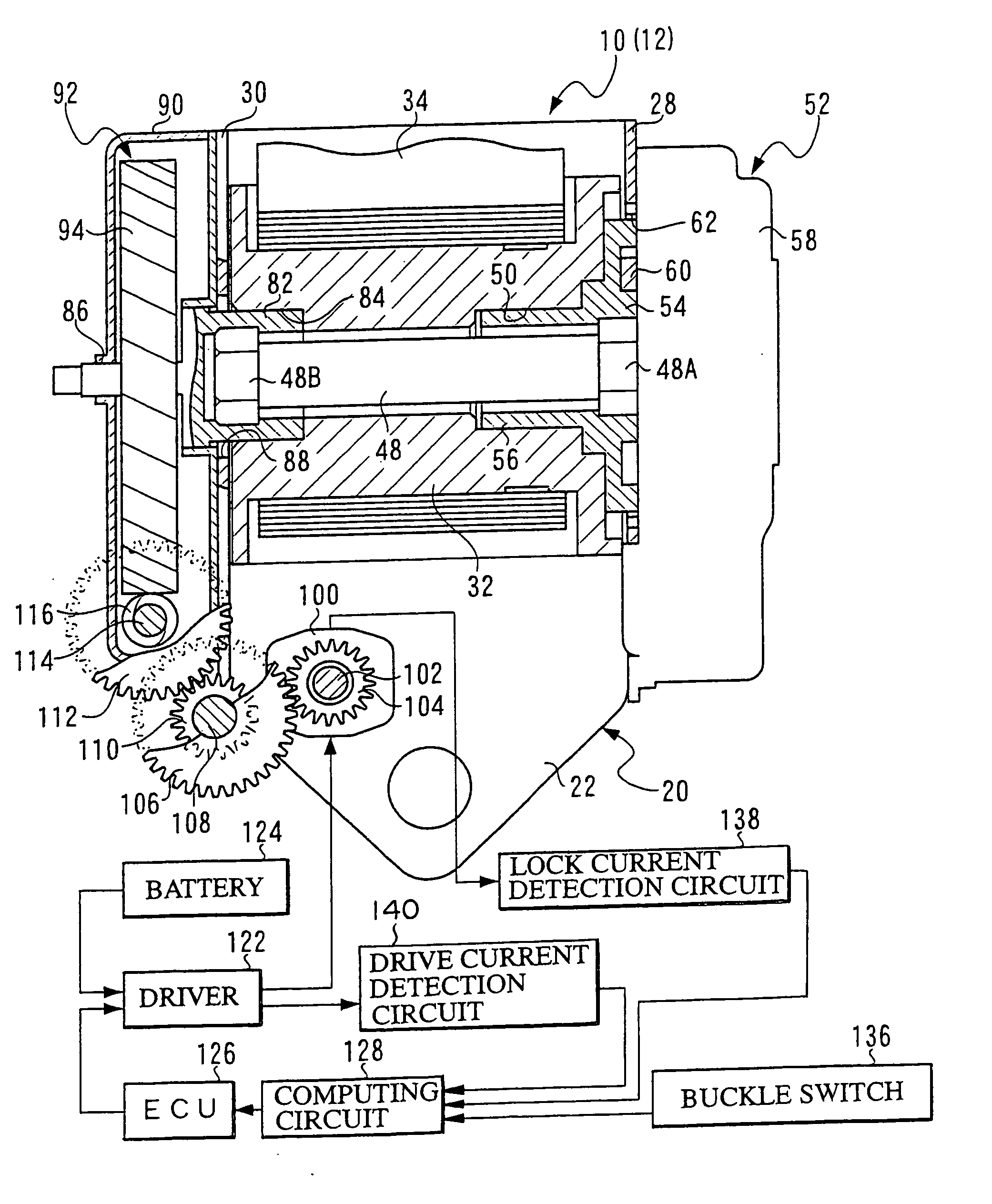
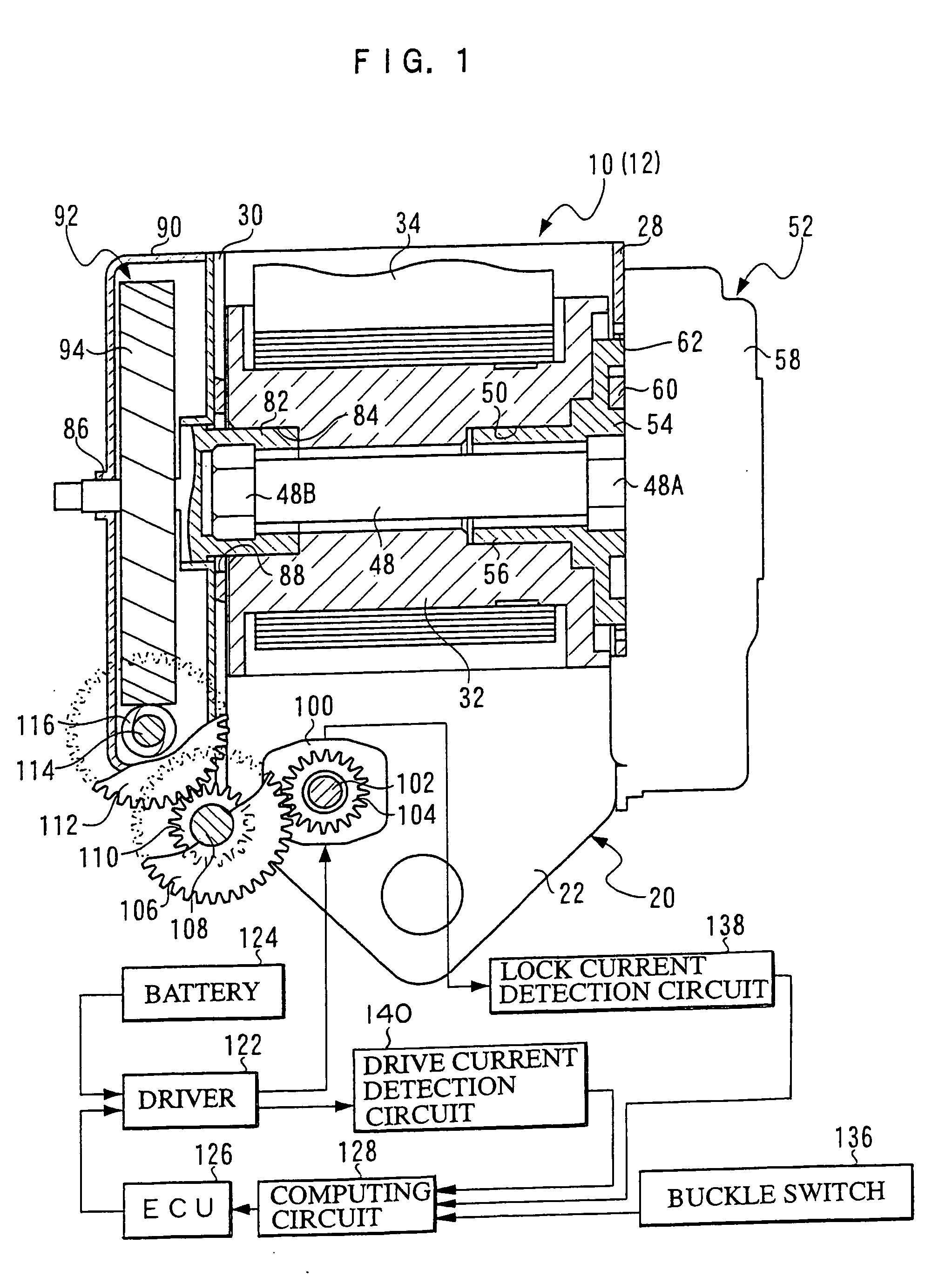
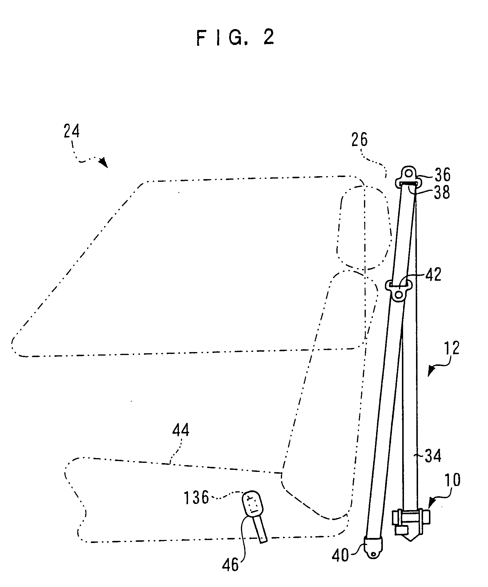
[0040]FIG. 1 is a front sectional view showing the overall schematic configuration of a webbing take-up device 10 pertaining to an embodiment of the invention, and FIG. 2 is a side view showing the schematic configuration of a seat belt device 12 to which the webbing take-up device 10 has been applied.

[0041] As shown in FIG. 1, the webbing take-up device 10 is disposed with a frame 20. The frame 20 is disposed with a tabular back plate 22. The back plate 22 is fixed, by unillustrated fixing means such as a bolt, to a vehicle body in the vicinity of a lower end portion of a center pillar 26 (see FIG. 2) of a vehicle 24. Thus, the webbing take-up device 10 is attached to the vehicle body.

[0042] A pair of leg plates 28 and 30 that face each other in the substantial front-rear direction of the vehicle 24 extend parallel to each other from both width-direction ends of the back plate 22.

[0043] A spool 32 is disposed so that its axial direction coincides ...


PUM


Abstract

In a webbing take-up device, when the release of a webbing belt is detected from the signal of a buckle switch, a motor starts driving, the webbing belt is taken up, and a computing circuit increases a voltage Eb in accordance with an integrated time after the signal is switched. In this state, a lock current flows due to an output shaft of the motor being stopped, and when the power to the motor is cut off by increasing the lock current, the values of voltages El and Ed respectively corresponding to the integrated time in which the lock current is powered and the integrated time in which the power to the motor is cut off are subtracted from the value of the voltage Eb, and the motor is driven until the computing result reaches a predetermined value.

Description

CROSS-REFERENCE TO RELATED APPLICATION [0001] This application claims priority under 35 USC 119 from Japanese Patent Application No. 2004-224108, the disclosure of which is incorporated by reference herein. BACKGROUND OF THE INVENTION [0002] 1. Field of the Invention [0003] The present invention relates to a webbing take-up device that configures a seat belt for restraining, with a long band-like webbing belt, the body of a vehicle occupant seated in a seat of a vehicle. [0004] 2. Description of the Related Art [0005] Seat belt devices that restrain, with a long band-like webbing belt, the body of a vehicle occupant seated in a seat of a vehicle, are disposed with a webbing take-up device fixed to the vehicle body at the side of the seat. The webbing take-up device is disposed with a spool (take-up shaft) whose axial direction is along the substantial front-rear direction of the vehicle, for example. A longitudinal-direction base end side of the webbing belt is attached to the spool...

Claims


Application Information

Patent Timeline
Patent Type & Authority Applications(United States)
IPC IPC(8): B60R22/46
CPCB60R2022/444B60R22/44
Inventor KOIDE, TERUHIKONOJIRI, MASAYOSHIMUTO, KOJI
Owner KK TOKAI RIKA DENKI SEISAKUSHO
Why Eureka
Try Eureka