Wire accommodation apparatus

a technology of wire holding and wire housing, which is applied in the field of wire holding apparatus, can solve the problems of large number of optical parts and electronic parts that are highly densely mounted, require space for accommodating excessive portions, and are partly excessively long and slack, and achieve high reliability and efficient wire holding operation.

Inactive Publication Date: 2010-03-23
FUJITSU LTD
View PDF3 Cites 1 Cited by
  • Summary
  • Abstract
  • Description
  • Claims
  • Application Information

AI Technical Summary

Benefits of technology

[0023]An object of the present invention, which was made in view of the above points, is to provide a highly reliable wire accommodating apparatus by which a wire holding operation can be carried out efficiently.

Problems solved by technology

Further, there is a tendency that a larger number of optical parts and electronic parts are highly densely mounted on a substrate.
When the respective communication parts mounted on the substrate are connected to each other by the wires so that they can make communication, since the wires are formed longer than the distances between the respective communication parts, they are partly excessively long and slack.
When the excessive portions of the wires are accommodated in a wound state, since the entire lengths of the wires are not uniform and have a large dimensional dispersion (allowance), a space for accommodating the excessive portions is required.

Method used


Image

  • Wire accommodation apparatus
  • Wire accommodation apparatus
  • Wire accommodation apparatus

Examples


Embodiment Construction

[0049]An embodiment of the present invention will be explained below.

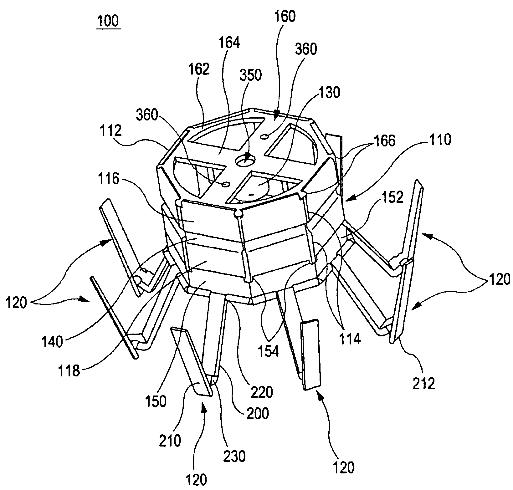
[0050]FIGS. 6 and 7 are views showing the embodiment of a wire accommodating apparatus according to the invention. As shown in FIGS. 6 and 7, the wire accommodating apparatus 100 has a cylindrical portion 110 around which wires connected to signal transmission parts are wound, a plurality of wire holding portions 120, which incline externally from the bottom of the cylindrical portion 110 as well as are disposed so as to pivot with respect to the cylindrical portion 110, and a fixed portion 130 formed on the inside of the cylindrical portion 110 so as to project downward and inserted into and fixed to an attachment hole of the to-be-mounted member.

[0051]Note that, in the explanation of the embodiment, although an optical fiber cable for transmitting an optical signal is exemplified as the wire wound around the cylindrical portion 110, the wire may also be a conductive cable for transmitting an electric signal.

[0052...


PUM


Abstract

A wire accommodating apparatus includes a cylindrical portion around which a wire connected to a signal transmission part is wound; a number of wire holding portions which incline externally from the bottom of the cylindrical portion and are disposed pivotably; and a fixed portion formed in the cylindrical portion so as to project downward, passing through an attachment hole of a to-be-mounted member, and fixed therein.

Description

CROSS-REFERENCE TO RELATED APPLICATION[0001]This application is based upon and claims the benefit of priority of the prior Japanese Patent Application No. 2008-041152, filed on Feb. 22, 2008, the entire contents of which are incorporated herein by reference.1. BACKGROUND[0002]The present invention relates to a wire accommodating apparatus, and more specifically to a wire accommodating apparatus arranged so as to compactly accommodate the excessive portions of wires, such as optical fibers and electric wires, connected to optical parts or electronic parts for transmitting a signal.2. DESCRIPTION OF THE RELATED ART[0003]A lot of communication optical parts and electronic parts for transmitting a signal by communication are mounted on a substrate mounted on an electronic apparatus having a communication function, such as communication equipment, and the respective communication parts (optical parts and electronic parts) are connected to each other through wires, such as optical fibers ...

Claims


Application Information

Patent Timeline
Patent Type & Authority Patents(United States)
IPC IPC(8): G02B6/00G02B6/36G02B6/38H01R39/00H01R4/38
CPCG02B6/4457
Inventor TSUTSUMI, KENJIWAKAO, MANABUKURAMITSU, KOUICHI
Owner FUJITSU LTD
Why Eureka
Try Eureka