

Patella reference device
- Summary
- Abstract
- Description
- Claims
- Application Information
AI Technical Summary
Benefits of technology
Problems solved by technology
Method used
Image

Examples
Embodiment Construction
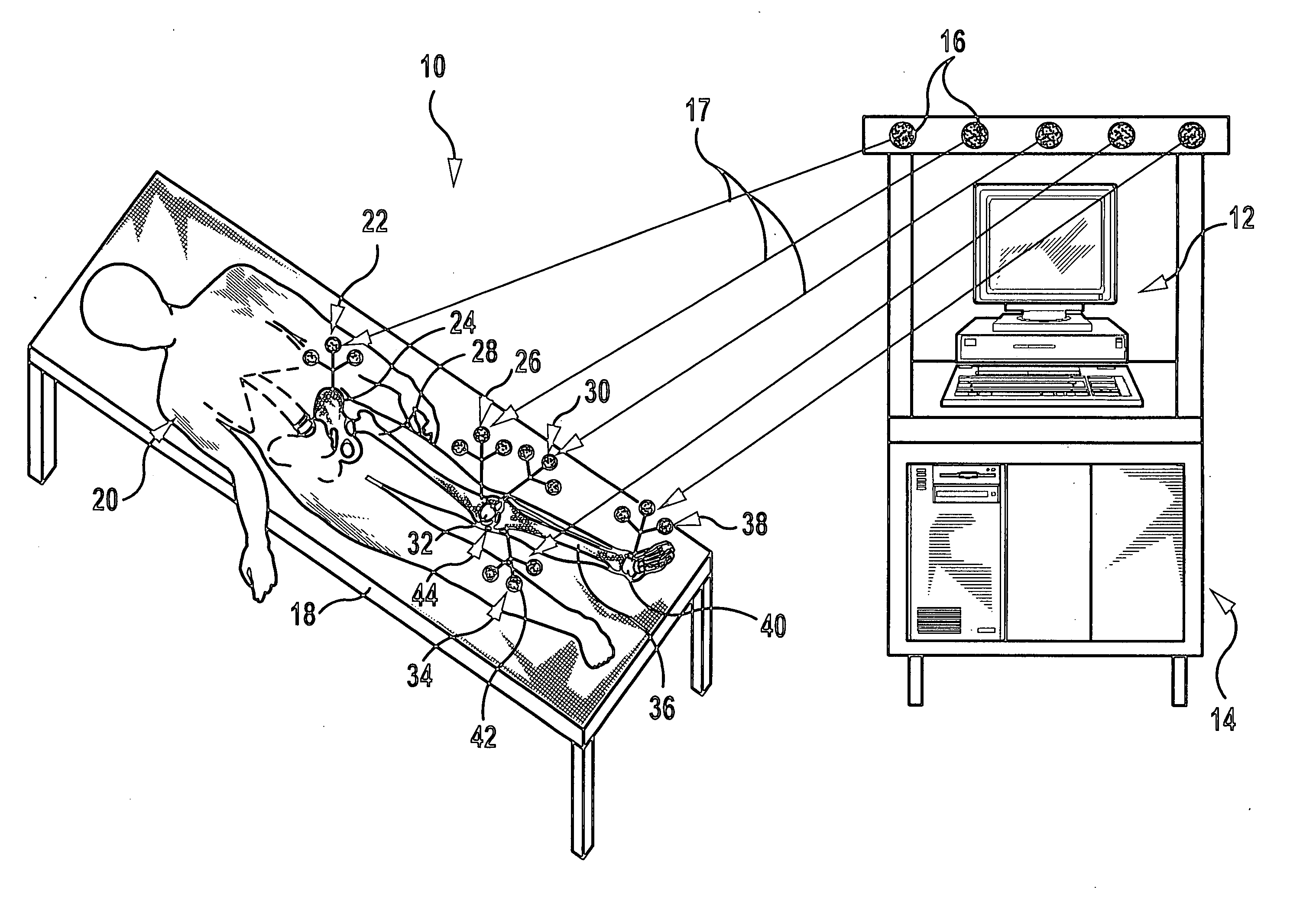
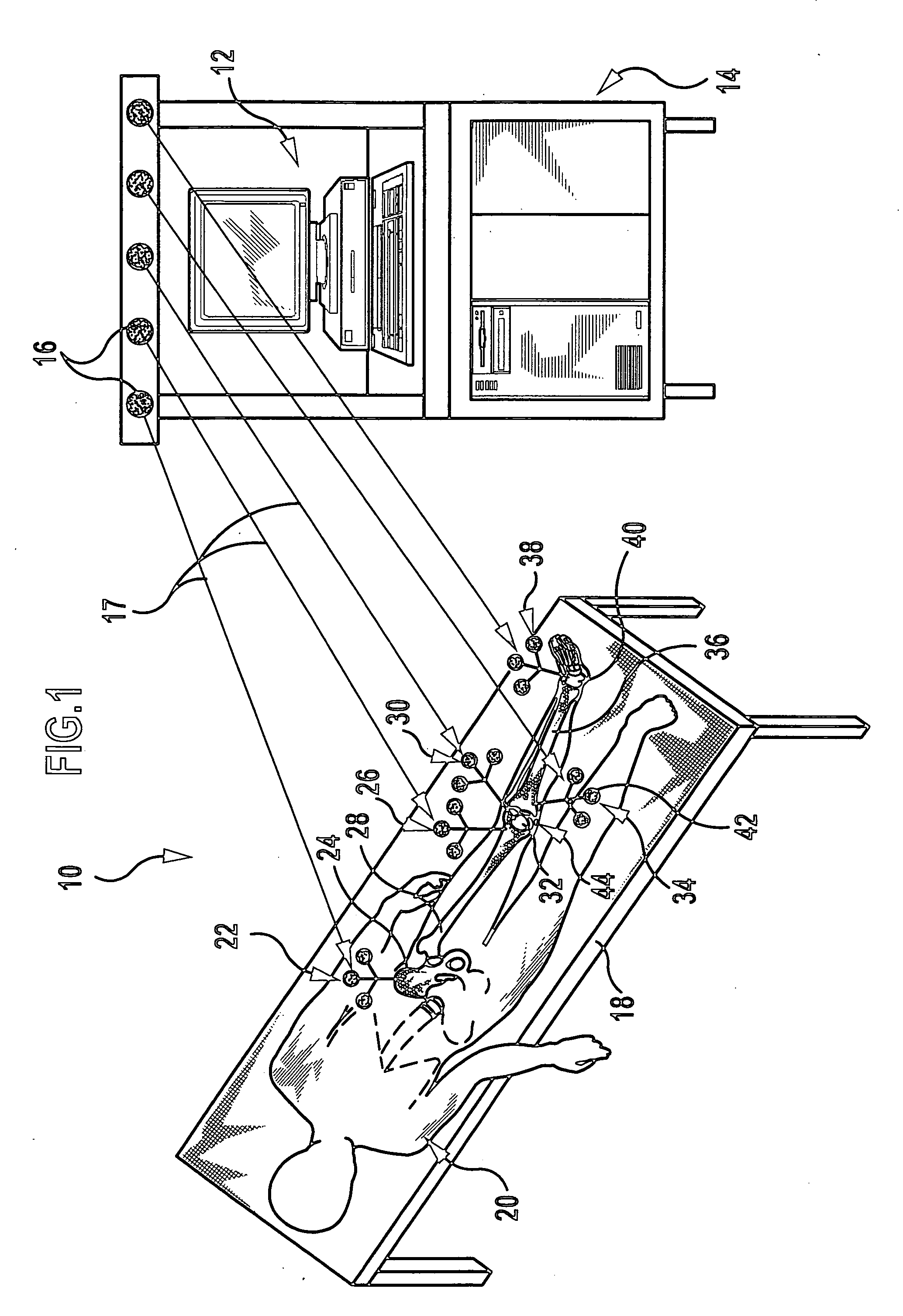
[0045]FIG. 1 shows a navigation system given the reference 10 overall for conducting navigated surgical procedures on the human body. It comprises a transmitter and receiver station 14, which is controlled by computer and has several transmitter / receiver units 16 for transmitting and receiving electromagnetic radiation, as well as several reference elements for securing on a patient.
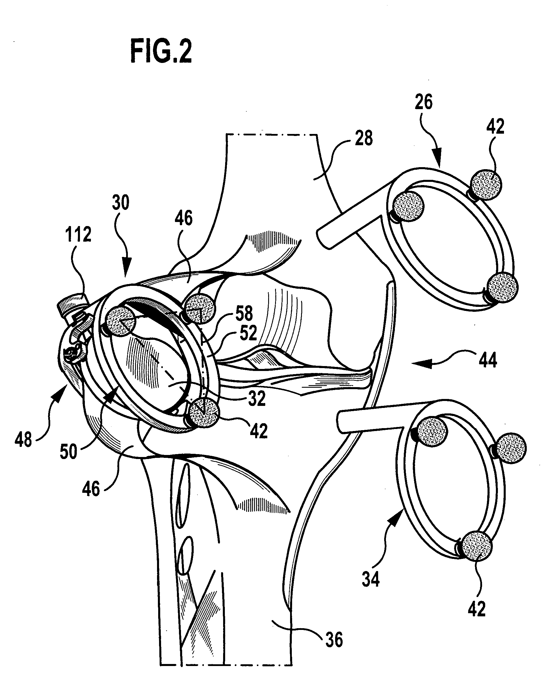
[0046] To conduct a navigated knee operation five reference elements are secured on a patient 20 lying on an operating table 18, i.e. a hip marker 22 on the pelvic bone 24, a femur marker 26 in the region of a femur 28 close to the knee, a patella marker 30 according to the invention on the patella 32, a tibia marker 34 in the region of a tibia 36 close to the knee and an ankle joint marker 38 on an ankle joint 40. Each of said markers 22, 26, 30, 34, 38 comprises three identical reflector spheres 42 that reflect electromagnetic radiation 17, which is transmitted by the transmitter / receiver units 16 and...
PUM
 Abstract
Description
Claims
Application Information