Cup cover structure

Inactive Publication Date: 2006-03-16
WANG CHING YUAN
View PDF4 Cites 3 Cited by
  • Summary
  • Abstract
  • Description
  • Claims
  • Application Information

AI Technical Summary

Benefits of technology

[0008] Therefore, it is the primary objective of the present invention to provide a cup cover structure, which comprises a circular cover and the area of the circular cover can be varied according to the size of the cup body; at least one light emitting device or sound amplifier disposed around the periphery of a circular cover; and a control circuit disposed inside the circular cover for controlling the light emitting device or sound amplifier, and the control circuit is connected to a switch, such that when the cup cover structure is in use, the circular cover is sheathed around any cup body, and the switch is turned on, and the control circuit drives the light emitting device to emit light or the sound amplifier. The invention not only allows users to change the cup body from time to time according to their preference, but also satisfy children's curiosity for new matters. Besides, the manufacture of such cup body is not as complicated as the prior art, and thus can save the manufacturing cost.

Problems solved by technology

Cup is an indispensable item to our daily life; regardless of the materials it is made, a cup is still a cup, and even the cup is painted with different colors or various patterns, the patterns are still static, and such patterns can no longer attract children's interest after being used for a while and thus cannot achieve the purpose of encouraging them to drink water anymore.
Such arrangement not only makes the manufacturing complicated, but also requires the cup body to be manufactured according to the aforementioned patent to achieve the light emitting effect.
For children who like to have changes from time to time, such cup will lose its attraction after being used for some time.
Furthermore, the base must be able to accommodate the circuit board and the power supply, and thus the base must have a certain substantial height and a certain substantial weight, which could be a burden for children to use.

Method used


Image

  • Cup cover structure
  • Cup cover structure
  • Cup cover structure

Examples


Embodiment Construction

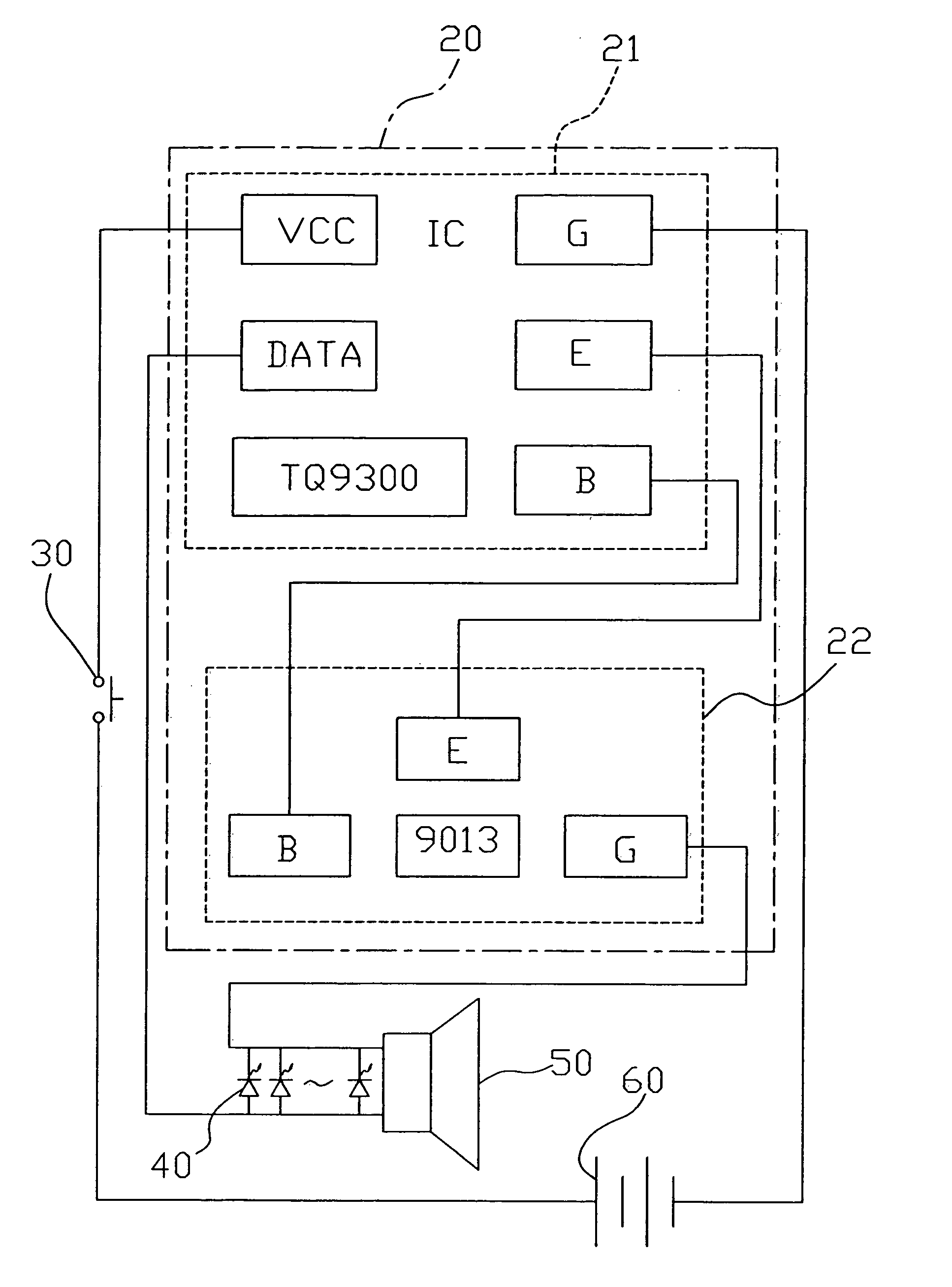
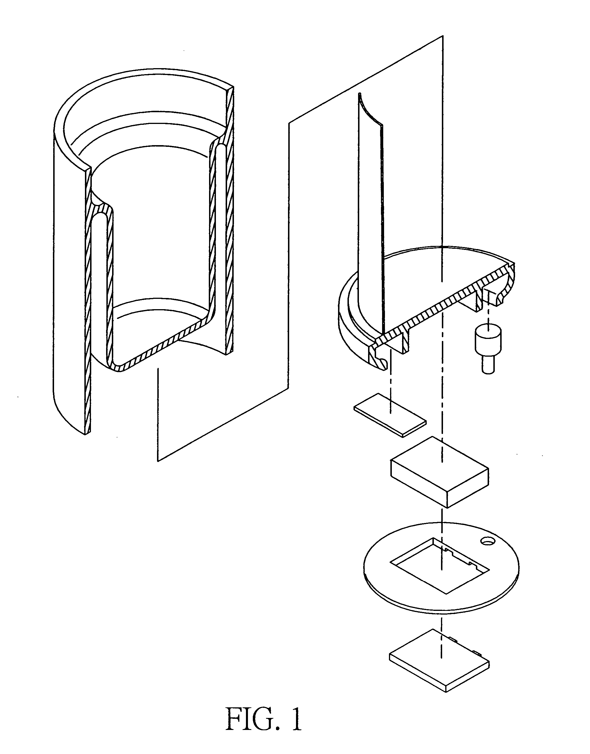
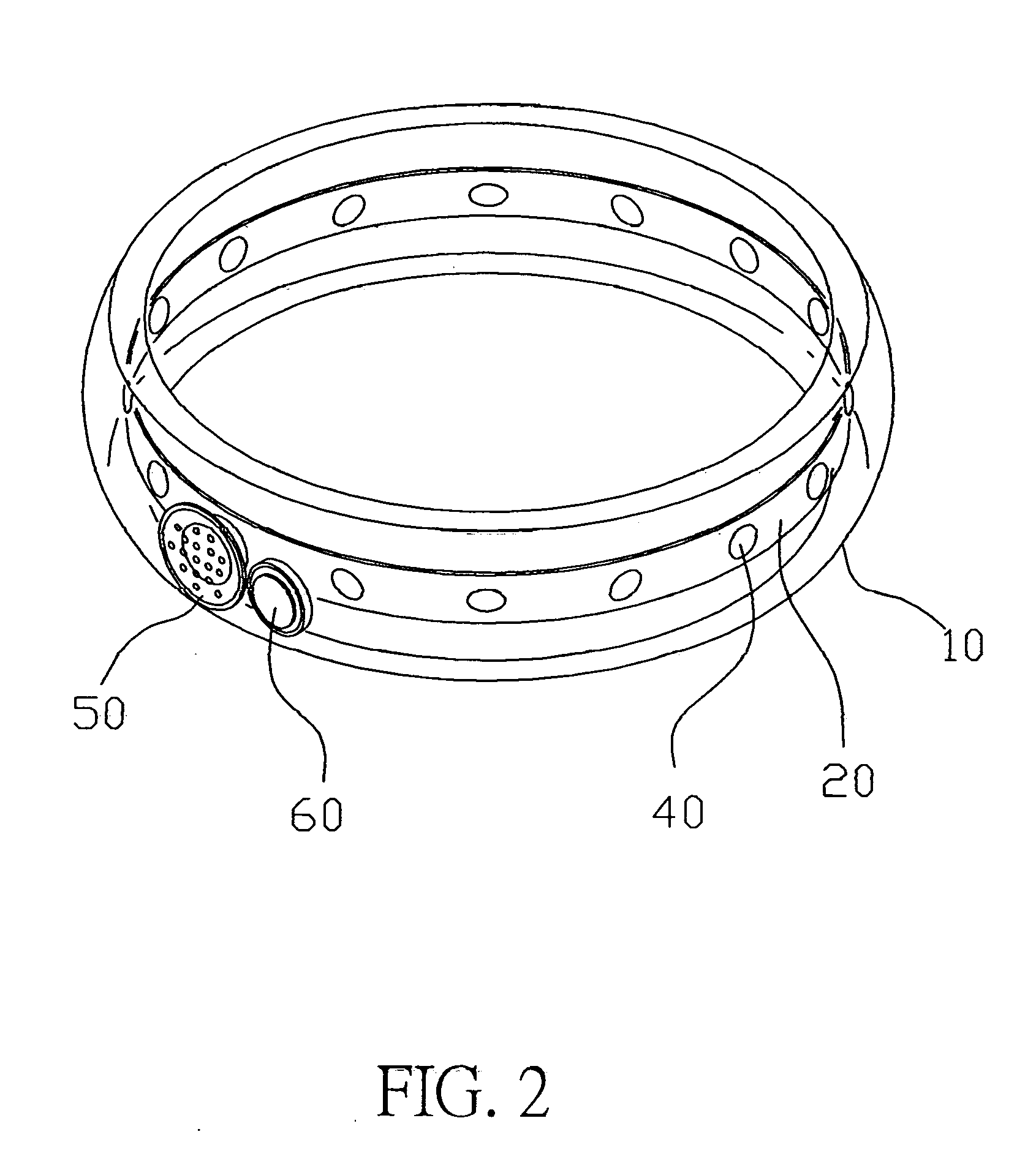
[0015] Please refer to FIGS. 2 and 5 for a cup cover structure according to the present invention. The cup cover structure comprises: a circular cover 10, and the circular cover 10 adopted by this embodiment is annular in shape but not limited to such shape, and the persons skilled in the art may change its shape; a control circuit 20 disposed in the circular cover 10 and the control circuit 20 is electrically connected to a switch 30, and the switch 30 could be a switching type switch or a mercury touch control type switch, and the control circuit 20 is electrically connected to at least one light emitting device 40 or sound amplifier 50 or both light emitting device 40 and sound amplifier 50, and the light emitting device 40 and the sound amplifier 50 are disposed around the periphery of the circular cover 10 and the light emitting 40 adopted by this embodiment is a light emitting diode and the sound amplifier 50 is a loudspeaker.

[0016] Please refer to FIG. 5. The control circuit...


PUM


Abstract

The present invention discloses a cup cover structure, which comprises at least one light emitting device or sound amplifier disposed around the periphery of a circular cover, and a control circuit disposed inside the circular cover for controlling the light emitting device or sound amplifier, and the control circuit is connected to a switch, such that when the cup cover structure is in use, the circular cover is sheathed around a cup, and the switch is turned on, and the control circuit drives the light emitting device to emit light or the sound amplifier to emit sound or simultaneously emit light and sound as to give more fun to children and attract their attention and curiosity as well as encourage them to drink more water.

Description

BACKGROUND OF THE INVENTION [0001] 1. Field of the Invention [0002] The present invention relates to a cup cover structure being sheathed onto a cup body and capable of emitting lights or sounds to attract children's attention and curiosity and providing a drinking cup with fin for children. [0003] 2. Description of the Related Art [0004] Cup is an indispensable item to our daily life; regardless of the materials it is made, a cup is still a cup, and even the cup is painted with different colors or various patterns, the patterns are still static, and such patterns can no longer attract children's interest after being used for a while and thus cannot achieve the purpose of encouraging them to drink water anymore. [0005] In view of the foregoing shortcoming, some people improved the cup structure by the technology as disclosed in R.O.C. Patent No. 87211563 (Publication No. 357587). Please refer to FIG. 1 for the cup structure disclosed in that patent, which relates to a light emitting...

Claims


Application Information

Patent Timeline
IPC IPC(8): B65D51/26G01D13/22
CPCA47G19/2227A47G2019/2244A47G2019/2238A47G23/0216
Inventor WANG, CHING-YUAN
Owner WANG CHING YUAN
Why Eureka
Try Eureka