Electrode lead

Active Publication Date: 2006-04-06
BIOTRONIK SE & CO KG
View PDF6 Cites 48 Cited by
  • Summary
  • Abstract
  • Description
  • Claims
  • Application Information

AI Technical Summary

Benefits of technology

[0017] These two properties do not exist in any known material up to now. Materials with low electrical resistance usually have a low bioresistance, and vice versa. According to the invention, this problem is solved with a thin layer of bioresistant material and high electrical resistance on a core of a material with low electrical resistance. If the material with the high electrical resistance is appropriately dimen

Problems solved by technology

To be avoided is the formation of a corrosion layer, which causes the electrical resistance to increase, wit

Method used


Image

  • Electrode lead
  • Electrode lead
  • Electrode lead

Examples


Embodiment Construction

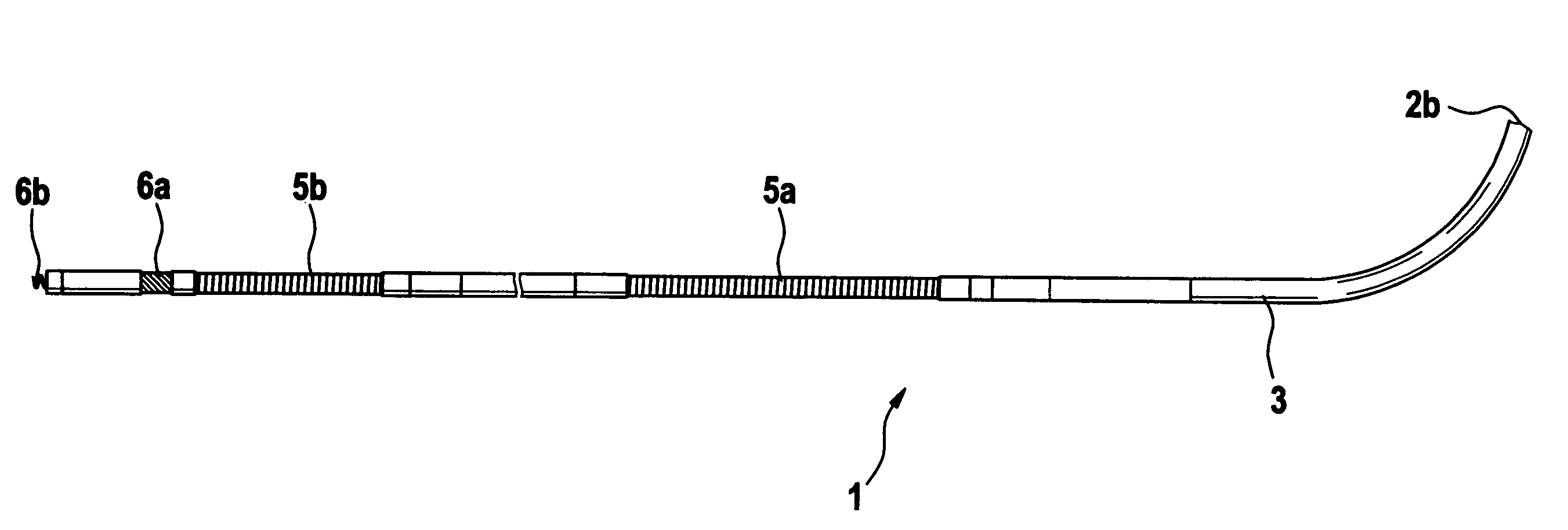
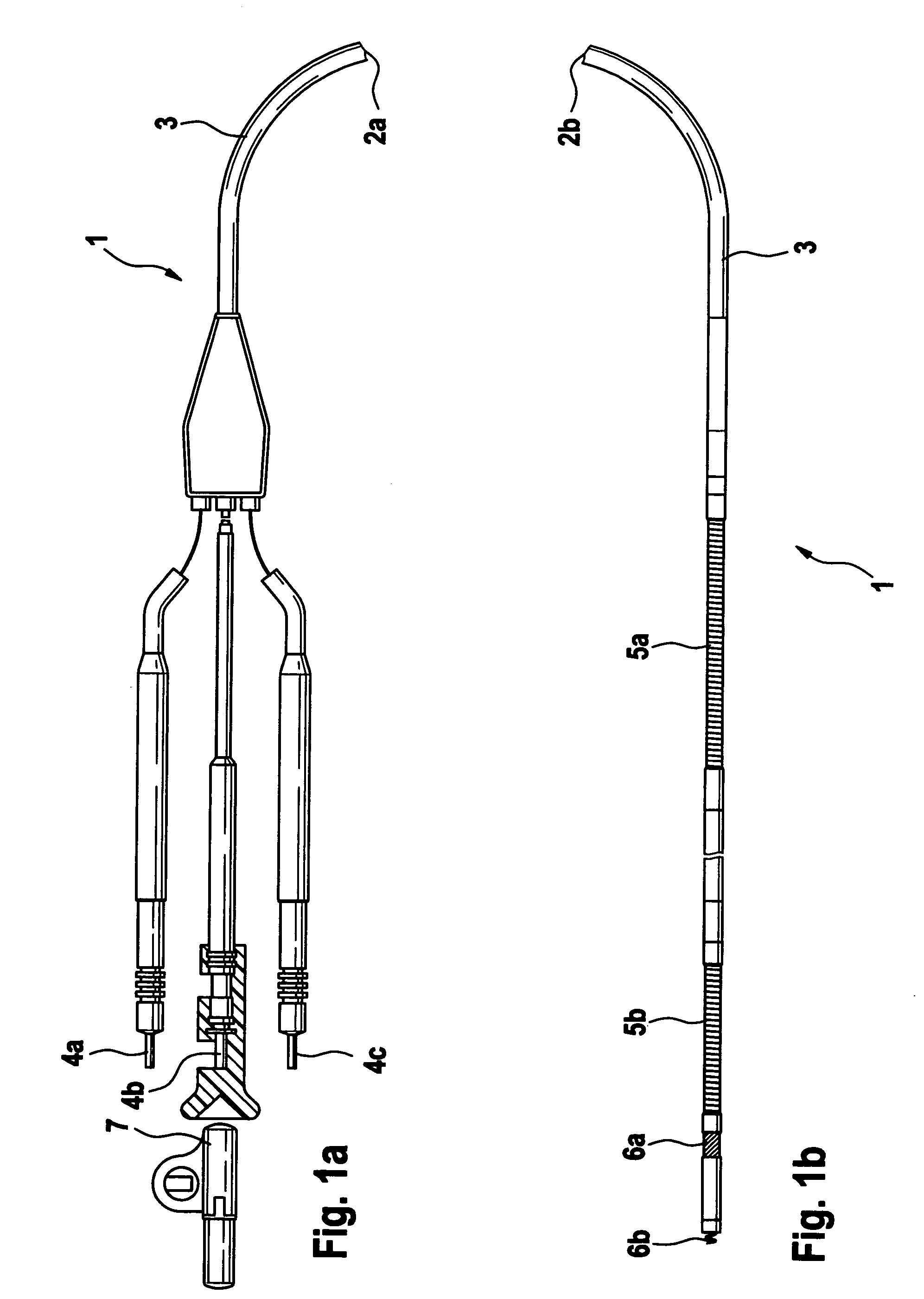
[0026]FIG. 1a shows the proximal region of a defibrillation electrode lead 1 having an electrode body 3 that is electrically insulated and sealed toward the outside, various proximal connectors 4a, 4b, and 4c for the electrical contact with an electrotherapeutic implantable device not visible here, and a partially visible guide wire 7, which ensures a reliable feeding of the electrode into the region of the heart being treated. The guide wire 7 is removed after the electrode has been successfully implanted.

[0027]FIG. 1b additionally shows the distal region of the defibrillation electrode lead 1 with an outwardly insulated and sealed electrode body 3 representing the electrically and therapeutically active region of the electrode. Shown are the different electrically active regions embedded in the electrode body 3, like under 5a and 5b two independent shock coils for delivering a therapeutic high-energy pulse to the cardiac tissue, and the two measuring electrodes 6a and 6b, which p...


PUM


Abstract

Implantable electrode lead for stimulation in or on the heart, comprising a body having an insulating and sealing outer surface, at least one electrical connection between an outwardly electrically active region having a connecting unit for the electrical connection to a cardiac pacemaker, cardioverter/defibrillator or other suitable electrically active implantable device, and an active or passive fixation. To reduce the electrical resistance while, at the same time, providing for a long life, the outwardly electrically active regions are manufactured with a component of high bioresistance, biocompatibility and non-toxicity, and a component with low electrical resistance.

Description

FIELD OF THE INVENTION [0001] The invention relates to an implantable electrode lead, in particular a defibrillation electrode lead, comprising at least one electrical conductor having a proximal connection region for an electrotherapeutic implantable device as well as at least one electrically active outer surface that is connectable via the conductor to the electrotherapeutic implantable device. BACKGROUND OF THE INVENTION [0002] Electrode leads of the generic type are well known from the prior art. They serve as an electrical connection between an electrotherapeutic implantable device, which may be a neurostimulator, pacemaker, defibrillator or other suitable electrotherapeutic implantable device, and the location being treated in the body. These may be whole variety of locations in the body. One example given here is a cardiac electrode lead. The electrode leads not only serve to transmit therapeutic pulses, but they also serve to transmit body and measurement signals to the imp...

Claims


Application Information

Patent Timeline
IPC IPC(8): A61N1/05
CPCA61N1/05A61N1/0563
Inventor BARTELS, KLAUSGUNTHER, THOMAS
Owner BIOTRONIK SE & CO KG
Why Eureka
Try Eureka