
Sound source location and quantification using arrays of vector probes
a vector probe and array technology, applied in direction finders using ultrasonic/sonic/infrasonic waves, instruments, reradiation, etc., can solve the problems of cumbersome and expensive probes, difficult to use a sufficient number of them to make simultaneous measurements at all points in the surrounding array, etc., to save time and effort, improve the accuracy of these methods
- Summary
- Abstract
- Description
- Claims
- Application Information
AI Technical Summary
Benefits of technology
Problems solved by technology
Method used
Image

Examples
Embodiment Construction
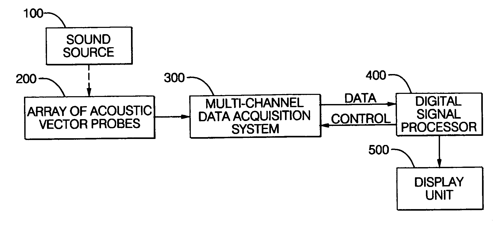
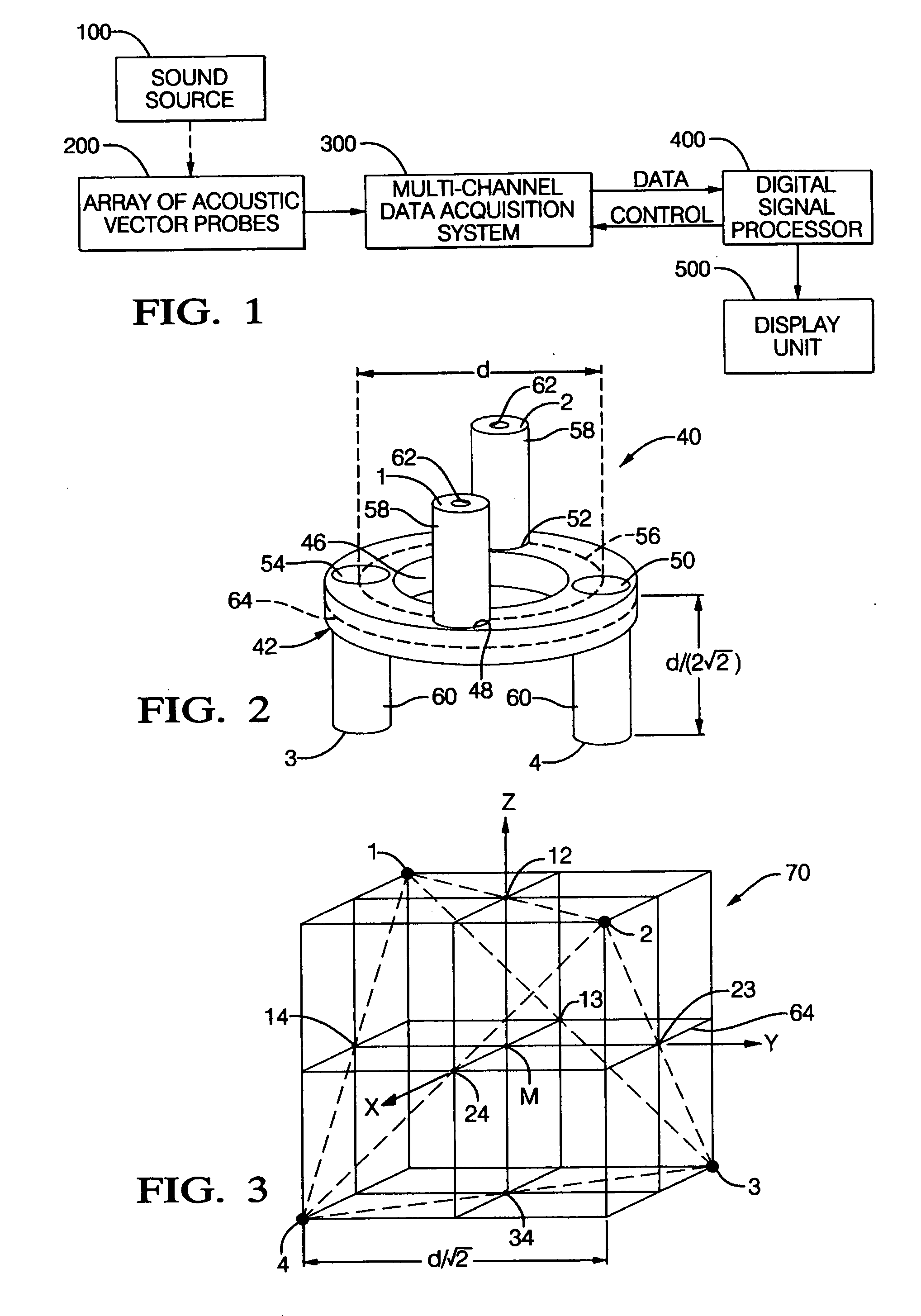
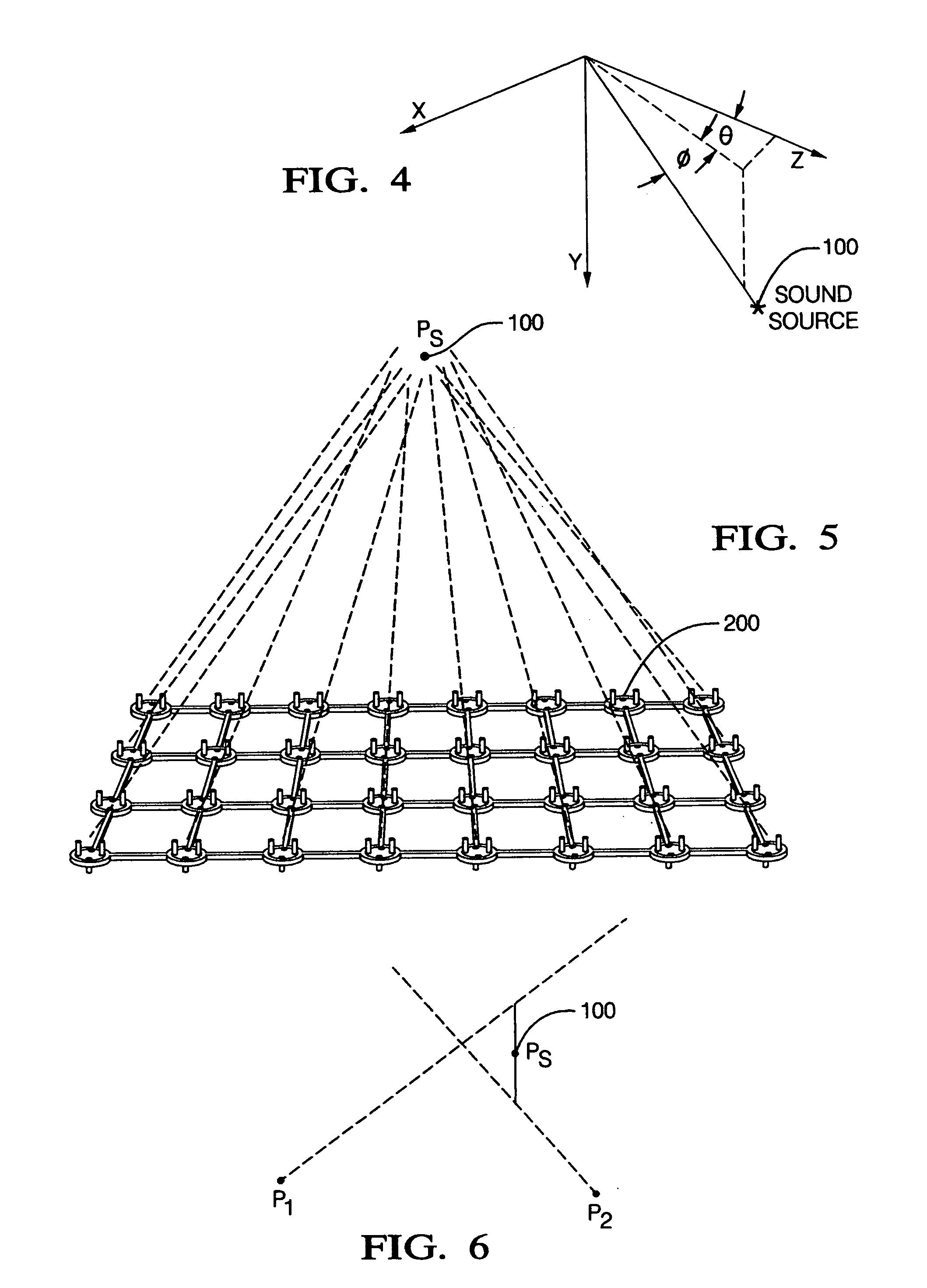
[0048]FIG. 1 is a block diagram illustrating the apparatus for source location and quantification of the present invention. Block 100 represents a sound source. Block 200 represents an array of AVPs. Block 300 represents a multi-channel data-acquisition system for rapid analog to digital conversion of the signals from the array, and for data storage, prior to input to the digital signal processor represented by block 400. The processor computes the three components of the sound-intensity vector and the sound pressure at each AVP in the array and interprets the data, displaying the results on an output device 500 such as a monitor screen. The sound-intensity vector is used to detect, position and quantify sound sources. The sound-pressure measurements can be phased to form a sensitivity beam.
[0049] In FIG. 2 numeral 40 generally indicates an AVP formed in accordance with the invention. Probe 40 includes a fixture 42 being an annular member formed as a ring with a central opening 46....
PUM
 Abstract
Description
Claims
Application Information