Fixture for anchoring in jaw bone

a technology for fixing and jaw bone, which is applied in the field of fixing jaw bone for anchoring, can solve the problems of unsatisfactory or defective fixture installation, interfering with bone threading, etc., and achieves the effect of maintaining the thread profile, narrowing the design of the tip, and facilitating entry

Active Publication Date: 2006-06-01
NOBEL BIOCARE SERVICES AG
View PDF8 Cites 11 Cited by
  • Summary
  • Abstract
  • Description
  • Claims
  • Application Information

AI Technical Summary

Benefits of technology

[0009] In one embodiment, a dental implant comprises a front portion which from the point of view of diameter grows very much narrower and which is arranged with both a cutting function and a threading function and is thus able, upon contact with a hard bone portion or portions, to penetrate through these without causing any substantial tendency for displacement of the respective hard bone portion. Another embodiment, a further feature is that the thread, which can have one, two or more thread turns, extends along the greater part of the outer surface of the fixture and also down along the greatly narrowing portion while substantially maintaining its thread profile.
[0010] In yet another embodiment, a further feature is that the fixture is specifically adapted for holes with a considerably smaller diameter than the main diameter of the fixture. This is achieved by the greatly narrowing design of the tip, which facilitates entry even into under-prepared areas.
[0011] Another embodiment of the present invention comprises a dental implant for effective anchoring in a jaw bone with a combination of soft and hard bone portions or inlays. The implant is configured to be applied in a hole with a diameter that is substantially smaller than the diameter of the implant so as to produce a clamping effect on the implant from the soft bone portions. The implant comprises a proximal portion and a tapering front portion. The tapering front portion has an end surface, which from the point of view of the diameter of the implant is substantially narrower. The front portion comprises a cutting edge that is configured, upon contact with the hard bone portions, to penetrate through the hard bone portions without causing a substantial tendency for displacement of the implant, and a threaded portion which has at least one thread turns and extends from the proximal portion of the implant to the front portion while substantially maintaining a thread profile.
[0012] An advantage of the embodiments describe above is that they permit, in comparison with existing products, improved application of an implant into both in soft bone and also in soft bone with interspersed portions of hard bone.
[0013] According to a preferred embodiment, one or more porous outer layers are used which are arranged on the thread / thread turns and which ensure effective fusion of the fixture in the jaw bone.
[0014] With the above-described embodiments is thus possible to satisfy the abovementioned requirements for a much effective fixture installation. Double or multiple threads can be obtained by proven techniques and a more prominent feature in this respect is that the double or multiple thread will extend downward along the greatly narrowing front portion whose cutting function can also be designed in a known manner. The front end can effectively enter and penetrate through hard areas of the jaw bone when the fixture is being screwed into the hole. The proposed porous layers can be formed in a known manner. For example, they can consist of oxide layers of the type included in the TiUnit® fixtures sold on the market by Nobel Biocare.

Problems solved by technology

The present-day fixtures for soft bone which are applied in holes with a smaller diameter than the fixtures concerned have a limited ability to expand and penetrate the hard bone portions or equivalent in question, and instead have the result that the fixtures press the hard bone portions aside.
In addition, the hard bone portions may interfere with the threading of the bone.
All of this can result in unsatisfactory or defective fixture installations.

Method used


Image

  • Fixture for anchoring in jaw bone
  • Fixture for anchoring in jaw bone
  • Fixture for anchoring in jaw bone

Examples


Embodiment Construction

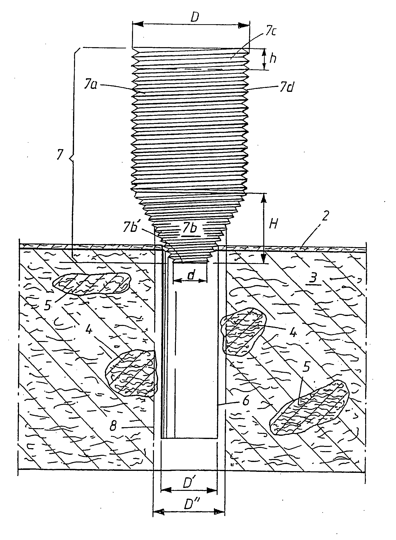
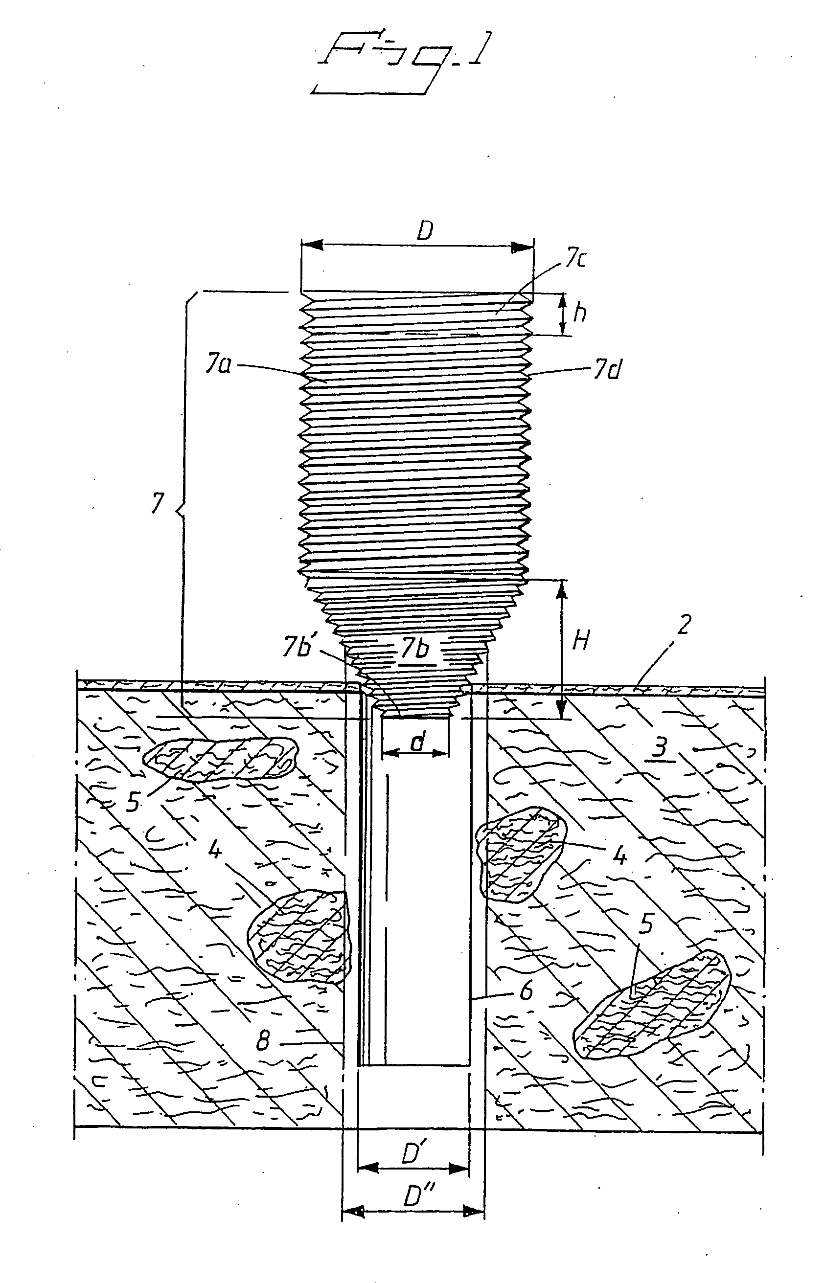
[0024] In FIG. 1, a jaw bone is indicated diagrammatically by reference number 1. The jaw bone can comprise different portions of bone. For example, a first layer of hard bone having been indicated by reference number 2, a second predominant layer of soft bone indicated by reference number 3, and islands of harder bone indicated by reference numbers 4 and 5. A hole 6 has been arranged in a manner known per se in the jaw bone. An illustrated embodiment of a fixture or dental implant 7, which is to be screwed into the hole, is also shown. The fixture 7 has a first or proximal part 7a which can be cylindrical or slightly conical. The fixture 7 also comprises a front or distal portion 7b which narrows greatly toward its front or distal end, from the point of view of its diameter. The fixture 7 also includes a collar-like attachment part 7c of substantially the same diameter D as the cylindrical part 7a.

[0025] The front end surface 7b′ on the front, greatly narrowing portion 7b has an e...


PUM


Abstract

To anchor a fixture in a jaw bone, the fixture is applied in a hole which is substantially smaller than the diameter of the fixture. The fixture has a front portion which from the point of view of diameter grows very much narrower and which is arranged with both a cutting function and a threading function. The fixture is provided with a thread, with one, two or more thread turns extending down along the greatly narrowing portion while substantially maintaining their thread profile. One or more porous layers arranged on the thread turns can also be included. In this way the fixture can exploit the clamping effect from the soft parts of the jaw bone and still effectively penetrate through any hard parts possibly present in the jaw bone, without these hard parts being pressed inward upon fixture application. An effective fusion of the fixture in the jaw bone is achieved with the aid of said porous outer layers.

Description

PRIORITY INFORMATION [0001] This application is a continuation of International Application PCT / SE2004 / 000532, with an international filing date of Apr. 6, 2004, which claims priority under 35 U.S.C. § 119 to Swedish Patent Application No. 0301149-1, filed Apr. 17, 2003, the entire contents of which are expressly incorporated by reference herein.BACKGROUND OF THE INVENTION [0002] 1. Field of the Invention [0003] The present invention relates to an arrangement in the form of a fixture for effective anchoring even in a jaw bone with a combination of soft and hard bone portions (or inlays / grafts), which fixture can be applied in a hole having a diameter smaller than the diameter of the fixture in order to produce a clamping effect on the implant from the soft bone portion or portions. [0004] 2. Description of the Related Art [0005] It is already known to adapt implants individually to soft and hard bones. Various implants and methods have been proposed to meet the different requirement...

Claims


Application Information

Patent Timeline
Patent Type & Authority Applications(United States)
IPC IPC(8): A61C8/00
CPCA61C8/0012A61C8/0022
Inventor CARVALHO, PAULO MALO
Owner NOBEL BIOCARE SERVICES AG
Why Eureka
Try Eureka