
Image processing method

Active Publication Date: 2009-05-07
WINTEK CORP
View PDF7 Cites 6 Cited by
  • Summary
  • Abstract
  • Description
  • Claims
  • Application Information

AI Technical Summary

Benefits of technology

[0010]The present invention is directed to an image processing method, by which image processing may be performed within a memory having relatively small volume, and the image processing method is conduce to improve an image contrast and achieve a colorful image while maintaining image hue unchanged.
[0024]According to the image processing method of the present invention, image signals to be input to every pixel unit are individually processed, so as to increase the contrast and the color saturation of the image of each pixel unit. Therefore, the image processing method of the present invention requires a relatively small memory volume, and applying of additional memory is not necessary, such that the cost and size of electronic device are reduced. Moreover, according to the image processing method of the present invention, a high image contrast and colorful image may be obtained while maintaining image hue unchanged.

Problems solved by technology

However, though the image contrast may be improved, the image brightness may be adjusted and the color saturation problem may be solved based on the histogram equalization technique, such technique may lead to a distortion of image hue and color saturation.
Moreover, the histogram equalization technique requires performing calculation on a large amount of data, and therefore additional frame memory is required, which may further increase complexity and cost of hardware.
However, if this method is applied to the pixel with high color saturation, a clipping phenomenon may be occurred to a portion of the image information, and original relatively fine solution of the image may be lost.
However, this method is performed based on adding add white color to the original image data, such that the image processed by this method may have a phenomenon of partial white.
Therefore, the above image processing methods all have their shortcomings, in which true presentation of original image hue cannot be achieved while simultaneously improving the color saturation and contrast of the image.

Method used


Image

  • Image processing method
  • Image processing method
  • Image processing method

Examples


first embodiment

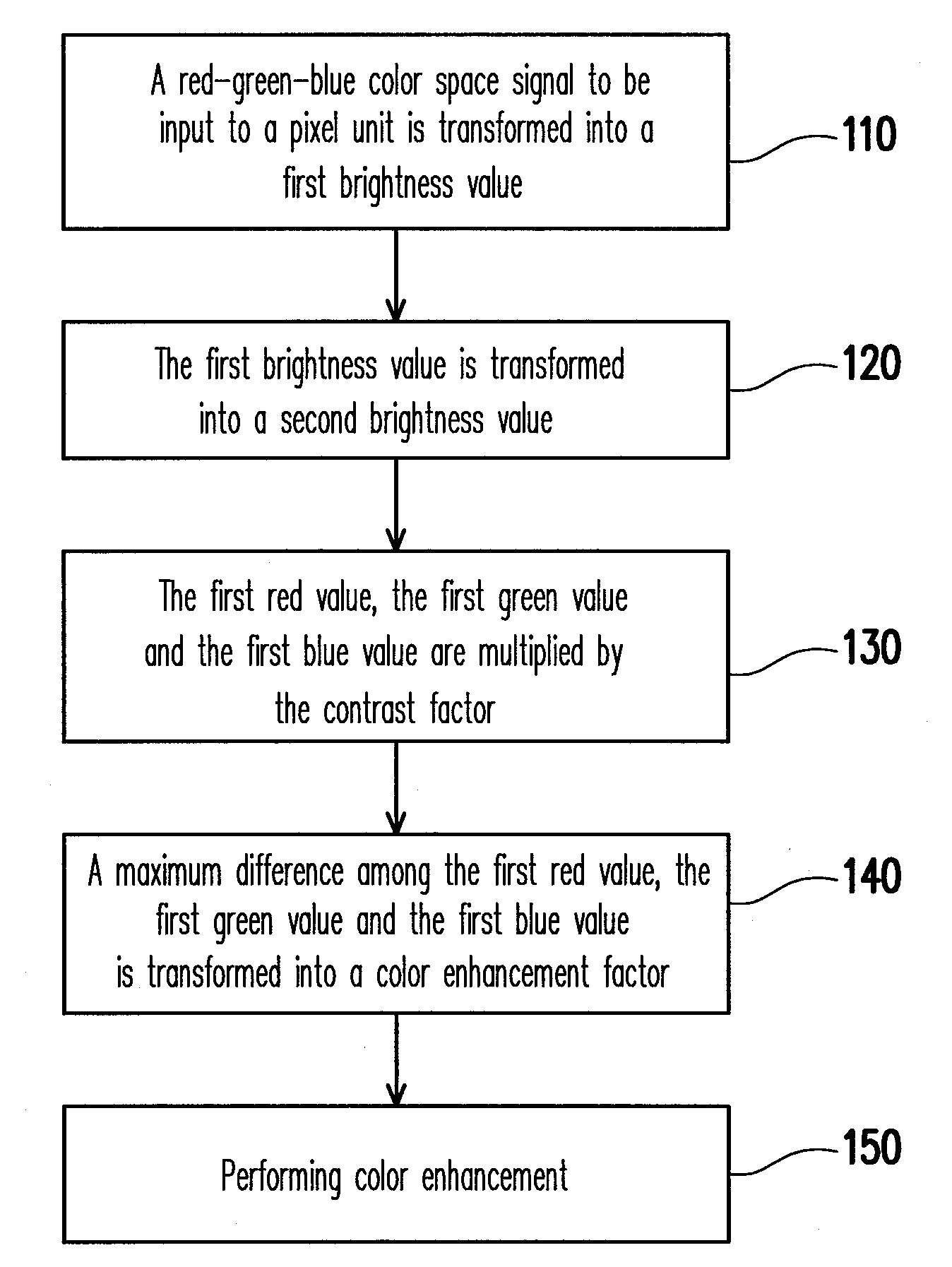
[0031]FIG. 1 is a flowchart illustrating an image processing method according to a first embodiment of the present invention. In the image processing method of the present invention, image signals to be displayed by every pixel unit are individually processed. First, referring to FIG. 1, in step 110, a red-green-blue color space signal to be input to a pixel unit is transformed into a first brightness value, wherein the red-green-blue color space signal includes a first red value, a first green value and a first blue value. More particularly, the red-green-blue color space signal is an image signal composed of red, green and blue sub-signals, i.e. a RGB color space signal, hereinafter, the red-green-blue color space signal is referred to as the RGB color space signal. In the present embodiment, the RGB color space signal is first transformed into a YUV color space signal, wherein Y signal is the first brightness value. Actually, if the first red value is R, the first green value is ...

second embodiment

[0045]Certainly, the present invention is not limited to the above image processing method. FIG. 3 is a flowchart illustrating another image processing method according to a second embodiment of the present invention. Referring to FIG. 3, in step 310, a maximum difference among a first red value, a first green value and a first blue value to be input to a pixel unit is transformed into a color enhancement factor. A relationship between the maximum difference and the color enhancement factor is similar to that of the first embodiment, namely, the greater the maximum difference is, the smaller the color enhancement factor is; and the smaller the maximum difference is, the greater the color enhancement factor is. In other words, the higher the color purity of the image data is, the lesser the image data is color enhanced, conversely, the lower the color purity of the image data is, the greater the image data is color enhanced.

[0046]Next, in step 320, a color enhancement is performed. A...

third embodiment

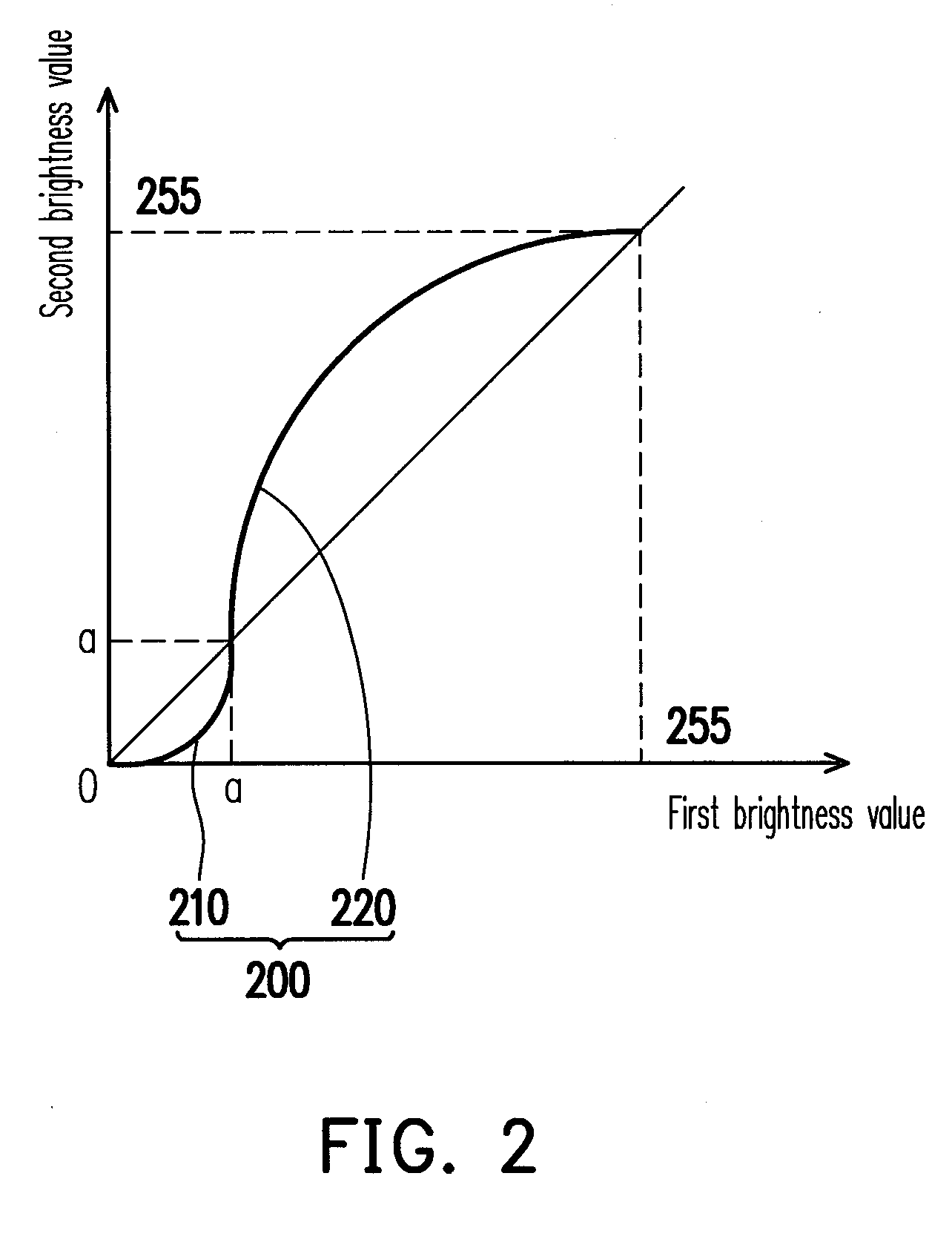
[0050]FIG. 4 is a diagram illustrating a curve for a curve function according to the third embodiment of the present invention. The image processing method of the third embodiment according to the present invention is substantially similar to the abovementioned embodiments. Referring to FIG. 4, the curve function 400 using in the image processing method of the third embodiment has a straight segment 410 and a curve segment 420. The straight segment 410 is corresponding to the range between less then “a” and greater then 0 and the curve segment 420 curves downward. According to the embodiment, if the first brightness value is less than “a” and is greater than 0, the second brightness value obtained based on calculation of the curve function 400 is equal to the first brightness value. If the first brightness value is greater than “a” and less than 255, the second brightness value obtained based on calculation of the curve function 400 is greater than the first brightness value. Furthe...


PUM


Abstract

An image processing method for individually processing an image of each pixel unit is provided. A red-green-blue color space signal to be input to a pixel unit is transformed into a first brightness signal. The red-green-blue color space signal includes a first red signal, a first green signal and a first blue signal. The first brightness signal is transformed into a second brightness signal to obtain a contrast factor, wherein the contrast factor is a ratio of the second brightness signal and the first brightness signal. The first red signal, the first green signal and the first blue signal are multiplied by the contrast factor to obtain a second red signal, a second green signal and a second blue signal. The second red signal, the second green signal and the second blue signal are performed by color enhancement to obtain a high contrast and colorful image.

Description

CROSS-REFERENCE TO RELATED APPLICATION[0001]This application claims the priority benefit of Taiwan application serial no. 96141850, filed on Nov. 6, 2007. The entirety of the above-mentioned patent application is hereby incorporated by reference herein and made a part of specification.BACKGROUND OF THE INVENTION[0002]1. Field of the Invention[0003]The present invention relates to an image processing method. More particularly, the present invention relates to an image processing method, which may individually process an image of each single pixel unit.[0004]2. Description of Related Art[0005]Image processing includes adjustment of image information such as color and brightness of an image. With a growing demand in high quality digital image, digital image processing technique is being rapidly developed. Regardless of how dark or how bright a digital image is, contrast, brightness and color saturation etc. of the digital image may be improved after the image processing.[0006]Presently...

Claims


Application Information

Patent Timeline
IPC IPC(8): G06K9/00
CPCH04N1/6027H04N1/407
Inventor LI, JYUN-SIANLAI, CHIH-CHANGHSU, CHING-FUWENG, RUEY-SHING
Owner WINTEK CORP
Learn More