Brushless motor pump

a brushless, motor technology, applied in the direction of piston pumps, pump control, fluid engines with non-positive displacement, etc., to achieve the effect of smooth operation and discharge of water, and minimal power us

Inactive Publication Date: 2006-07-13
HSU HSIANG YUAN
View PDF5 Cites 7 Cited by
  • Summary
  • Abstract
  • Description
  • Claims
  • Application Information

AI Technical Summary

Benefits of technology

[0013] Therefore, the object of the present invention is to provide a brushless motor pump that minimizes use of power, and that can operate and discharge water smoothly.

Problems solved by technology

Although the conventional pump can achieve its intended purpose, it nevertheless suffers from many drawbacks as follows:

Method used


Image

  • Brushless motor pump
  • Brushless motor pump
  • Brushless motor pump

Examples


Embodiment Construction

[0031] Before the present invention is described in greater detail, it should be noted that like elements are denoted by the same reference numerals throughout the disclosure.

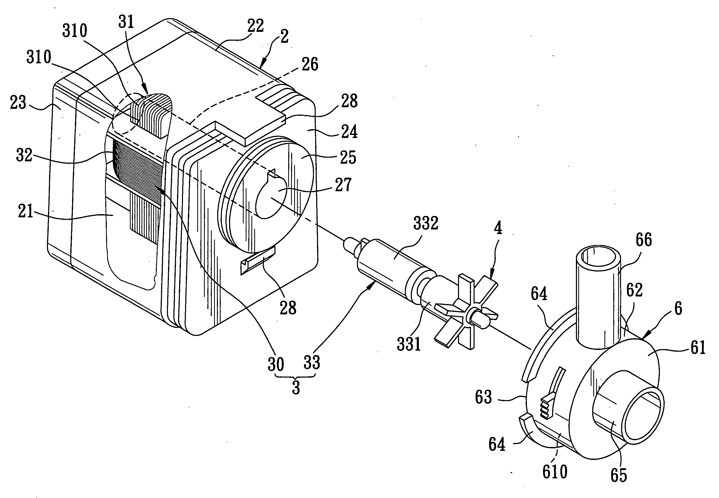
[0032] Referring to FIGS. 5 and 6, a brushless motor pump according to a first preferred embodiment of the present invention includes a case 2, a motor 3, a rotary blade assembly 4, a control unit 5, and a blade housing 6. The brushless motor pump may be a single-phase brushless motor pump.

[0033] The case 2 includes a main housing 22 that defines a chamber 21 therein. The main housing 22 has a rear end that is open, and a front end that is closed to form a front face 24. The case 2 also includes a rear cover 23 sealing the open rear end of the main housing 22. A circular boss 25 projects from the front face 24 of the main housing 22, and an opening is formed in the circular boss 25. A cylinder 26 is extended into the chamber 21 from the circular boss 25 starting from the opening 27. A pair of connectors 28 of...


PUM


Abstract

A brushless motor pump includes a case; a motor disposed in the case, and including a rotor and a stator; a rotary blade assembly connected to one end of the rotor; a blade housing mounted to the case and encompassing the rotary blade assembly; an excitation unit for energizing the stator; and a control unit for generating an operating frequency which increases gradually from an initial low value to a constant high value so that the rotor starts to operate at a low speed and continues its operation to a high constant speed.

Description

CROSS-REFERENCE TO RELATED APPLICATION [0001] This application claims priority of Taiwanese Application No. 094100632, filed on Jan. 10, 2005. BACKGROUND OF THE INVENTION [0002] 1. Field of the Invention [0003] The present invention relates to a pump, and more particularly to a brushless motor pump. [0004] 2. Description of the Related Art [0005] Referring to FIGS. 1 and 2, a conventional single-phase brushless motor pump 1 includes a motor 10, a hollow case 11, a fan blade member 14, and a front cover 15. [0006] The hollow case 11 includes a main housing 112 that defines a chamber 111 and has a front face 114. The case 11 further includes a circular boss 115 that projects from the front face 114 of the main housing 112, a cylinder 116 extended into the chamber 111 from the circular boss 115, an opening 117 formed in the circular boss 115 at a location corresponding to the cylinder 116, and a pair of L-shaped connectors 118 formed symmetrically about the circular boss 115. [0007] Th...

Claims


Application Information

Patent Timeline
Patent Type & Authority Applications(United States)
IPC IPC(8): F04B17/00
CPCF04D15/0066
Inventor HSU, HSIANG-YUAN
Owner HSU HSIANG YUAN
Why Eureka
Try Eureka