Camera-assisted adjustment of bonding head elements

Active Publication Date: 2006-07-20
HESSE
View PDF11 Cites 14 Cited by
  • Summary
  • Abstract
  • Description
  • Claims
  • Application Information

AI Technical Summary

Benefits of technology

[0007] It is an object of the invention to provide a method and/or an ultrasonic bonder by which accurate positioning

Problems solved by technology

Experience has shown that this is subject to considerable inaccuracies, since the operating user is reliant upon his own senses to achieve sufficiently accurate positioning of these elements with respect to one

Method used


Image

  • Camera-assisted adjustment of bonding head elements
  • Camera-assisted adjustment of bonding head elements
  • Camera-assisted adjustment of bonding head elements

Examples


Example

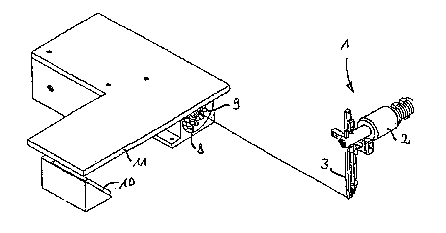
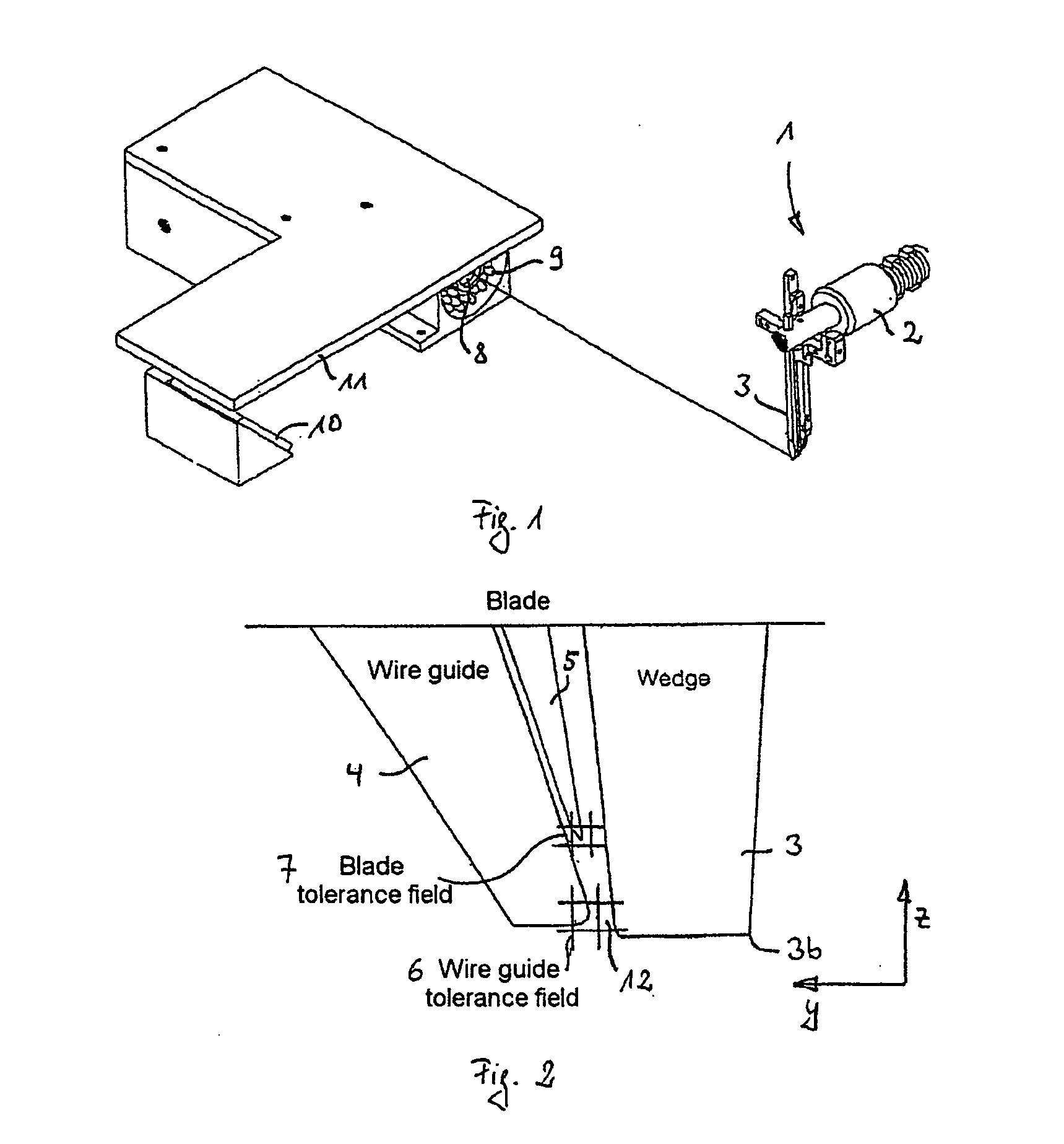
[0031]FIG. 1 shows a partial excerpt from an ultrasonic bonder with a bonding head 1 which is disposed thereon and in the usual way includes an ultrasonic transducer 2 which is provided on it and to which an ultrasonic tool in the form of a wedge 3 is secured. Furthermore, at the ultrasonic bonder, a camera 8, which in the illustration shown in FIG. 1 records a lateral view of the tip or the region around the tip of the ultrasonic tool 3, is provided on a corresponding holder.

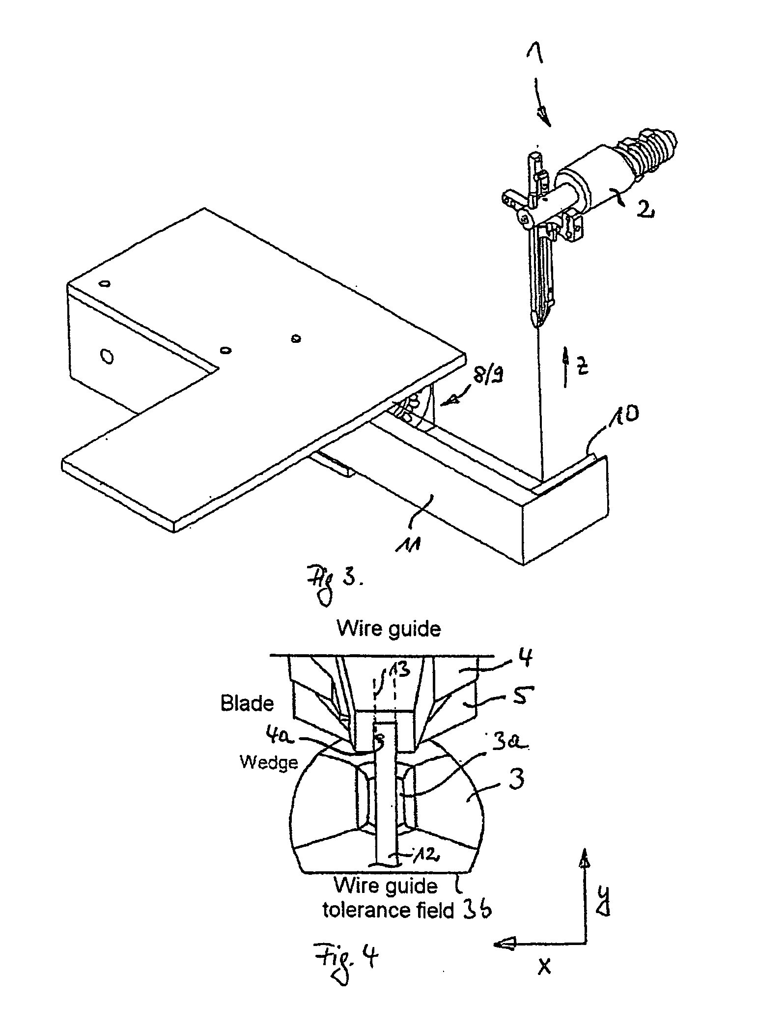
[0032]FIG. 2 shows a corresponding lateral image which can be viewed by a user on the display device of the camera, for example a screen. The relative arrangement of the wire guide 4 for supplying a wire 12 to the tip 3b of the ultrasonic tool 3 and of the blade 5 disposed between these elements with respect to the ultrasonic tool 3 can be clearly seen.

[0033] According to the invention, it is possible to provide that a user marks the front edge 3b of the tip of the ultrasonic tool, for example using a mouse p...


PUM

PropertyMeasurementUnit
Distanceaaaaaaaaaa
Optical propertiesaaaaaaaaaa

Abstract

The invention relates to a method which is used to carry out adjusting operations on a bond head, wherein a bond head element is positioned in relation to a reference element, especially an ultrasonic tool. According to the invention, at least the surrounding area of the reference element, especially the tip of the ultrasonic tool, is optically detected by means of a camera and is displayed in an image on a display device. A marking is superimposed in the display in order to facilitate positioning. The invention also relates to an ultrasonic bonder comprising a camera which is used to support the positioning of a bond head element. Said camera can optically detect at least the area surrounding the reference element, especially the tip of the ultrasonic tool.

Description

CROSS-REFERENCE TO RELATED APPLICATIONS [0001] This application is a continuation of International Patent Application No. PCT / EP2004 / 008018 filed on Jul. 17, 2004, which designates the United States and claims priority of German Patent Application No. 10338809.5 filed on Aug. 21, 2003.FIELD OF THE INVENTION [0002] The invention relates to a method and an apparatus for carrying out setting operations on a bonding head, in which a bonding head element is positioned relative to a reference element, such as for example an ultrasonic tool, in particular its tip. BACKGROUND OF THE INVENTION [0003] In the context of ultrasonic bonders which have a bonding head with an ultrasonic tool attached to it, for example for carrying out wire bonding, it is known that various bonding head elements have to be positioned relative to the ultrasonic tool and in particular relative to its tip. [0004] By way of example, accurate positioning of a wire feed relative to the tip of the ultrasonic tool is requ...

Claims


Application Information

Patent Timeline
IPC IPC(8): B23K20/00B23K20/10B23K5/20B23K1/06
CPCB23K20/10H01L2224/859H01L24/78H01L2224/78H01L2924/00014H01L2224/45099
Inventor WALTHER, FRANK
Owner HESSE
Why Eureka
Try Eureka