Computer, IO expansion device and method for recognizing connection of IO expansion device

Inactive Publication Date: 2006-08-10
FUJITSU LTD
View PDF11 Cites 2 Cited by
  • Summary
  • Abstract
  • Description
  • Claims
  • Application Information

AI Technical Summary

Benefits of technology

[0023] It is an object of the present invention to provide a computer, an IO expansion device and a method for recognizing a connection of IO expansion device capable of preventing erroneous connection between a computer main unit and PCI_Boxes provided as an IO expansion device, suitably monitoring and controlling connection or disconnection between the PCI_Boxes and the computer main unit on a partition-by-partition basis, and easily identifying the cause of a communication abnormality between the computer main unit and the PCI_Boxes at the time of occurrence of the communication abnormality.
[0026] According to the present invention, in the computer, it is possible to recognize the state of the IO expansion device being correctly corrected to the computer.
[0028] According to the present invention using the above-described arrangement, prevention of erroneous connection between the computer and the IO expansion device can be achieved with respect to each partition. Also, according to the present invention, connection / disconnection between the computer and the IO expansion device can be performed on a partition-by-partition basis.
[0031] The present invention also provides a method for recognizing a connection between a computer and an IO expansion device connecting at least an external IO device to the computer. The computer comprises an IO unit including an interface for connection to the IO expansion device, sending an output signal to the external IO device connected to the IO expansion device and receiving an input signal from the external IO device, and a monitoring and control unit including an interface for connection to the IO expansion device and monitoring and controlling the connection of the IO expansion device. The IO expansion device comprises an interface for connection to the IO unit, and an interface for connection to the monitoring and control unit. The method comprises transmitting, in the monitoring and control unit, a connection setting signal for setting the connection between the IO unit and the IO expansion device to the IO expansion device through the interface for connection between the monitoring and control unit and the IO unit and through the interface for connection between the IO unit and the IO expansion device on the basis of connection setting information on a setting of connection between the IO unit and the IO expansion device stored in advance in the monitoring and control unit, receiving, in the IO expansion device, the connection setting signal from the monitoring control unit and recording a connection state information on the state of connection between the IO unit and the IO expansion device, and obtaining, in the monitoring and control unit, the connection state information recorded by the IO expansion device by reading the connection state information at least through the interface for connection between the monitoring and control unit and the IO expansion device, and recognizing the connection between the IO unit and the IO expansion device on the basis of the result of comparison between the obtained connection state information and the connection setting information stored in advance. According to the present invention, erroneous connection between the computer and the IO expansion devices can be prevented.
[0033] In the present invention, a monitoring and control circuit for controlling an IO expansion device (for example PCI_Box) which are connected to a computer main unit is implemented as a comparatively simple piece of hardware at a low cost to monitor the states of connections between the computer main unit and the PCI_Boxes.
[0037] Thus, according to the present invention, connection / disconnection between the computer main unit and the PCI_Boxes can be performed on a partition-by-partition basis. Also, prevention of erroneous connection between the computer and the IO expansion device can be achieved with respect to each partition.

Problems solved by technology

In some cases, a function deficiency occurs at the time of fine partitioning if IO functions in a computer main unit alone are used.
No system capable of an operation including partitioning in a PCI_Box has been provided.
Therefore, there is a problem that when a communication abnormality occurs between the computer main unit 60 and one PCI_Box, the time taken to identify a fault point corresponding to the cause of communication abnormality is considerably long.

Method used


Image

  • Computer, IO expansion device and method for recognizing connection of IO expansion device
  • Computer, IO expansion device and method for recognizing connection of IO expansion device
  • Computer, IO expansion device and method for recognizing connection of IO expansion device

Examples


first embodiment

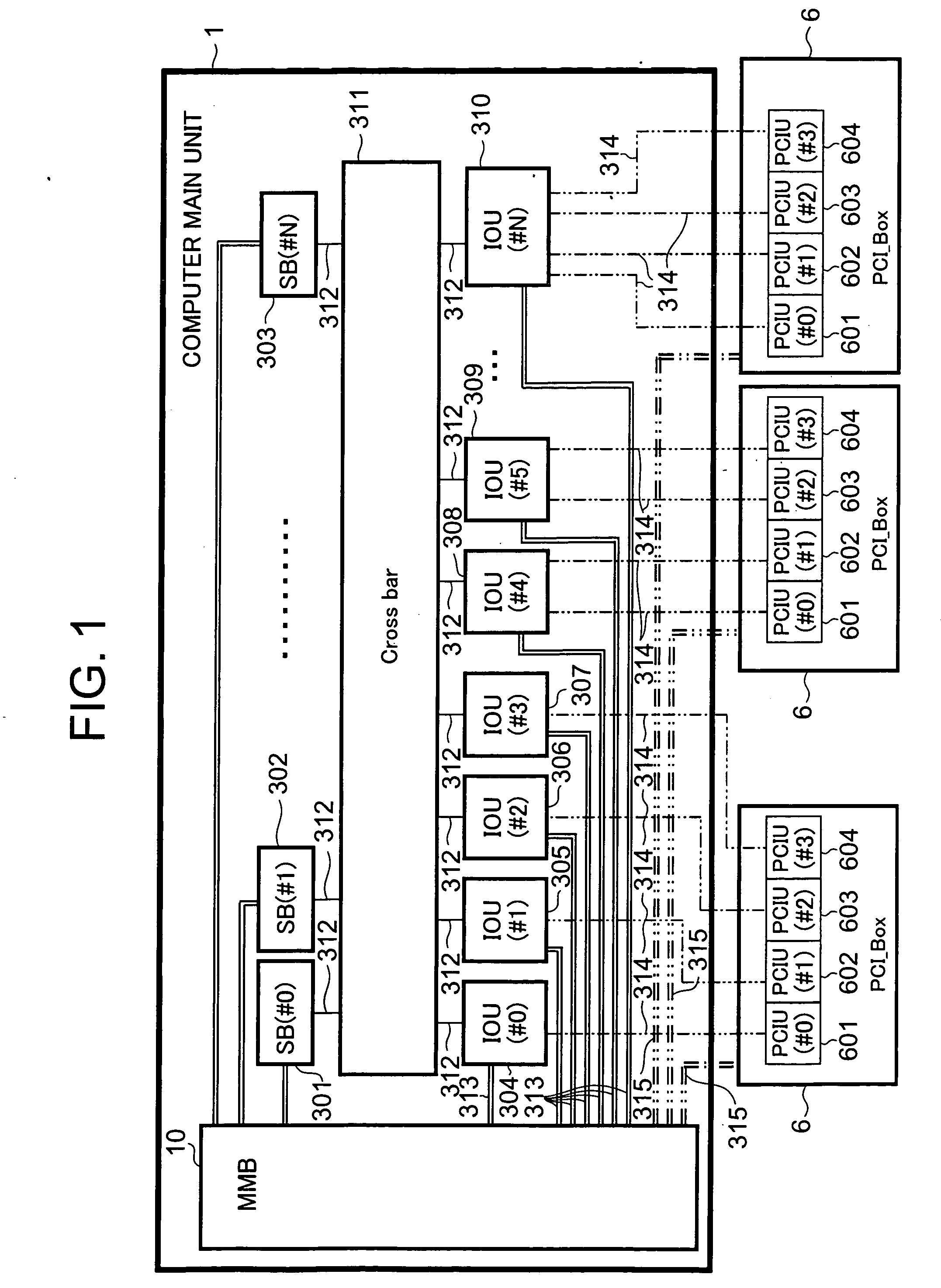
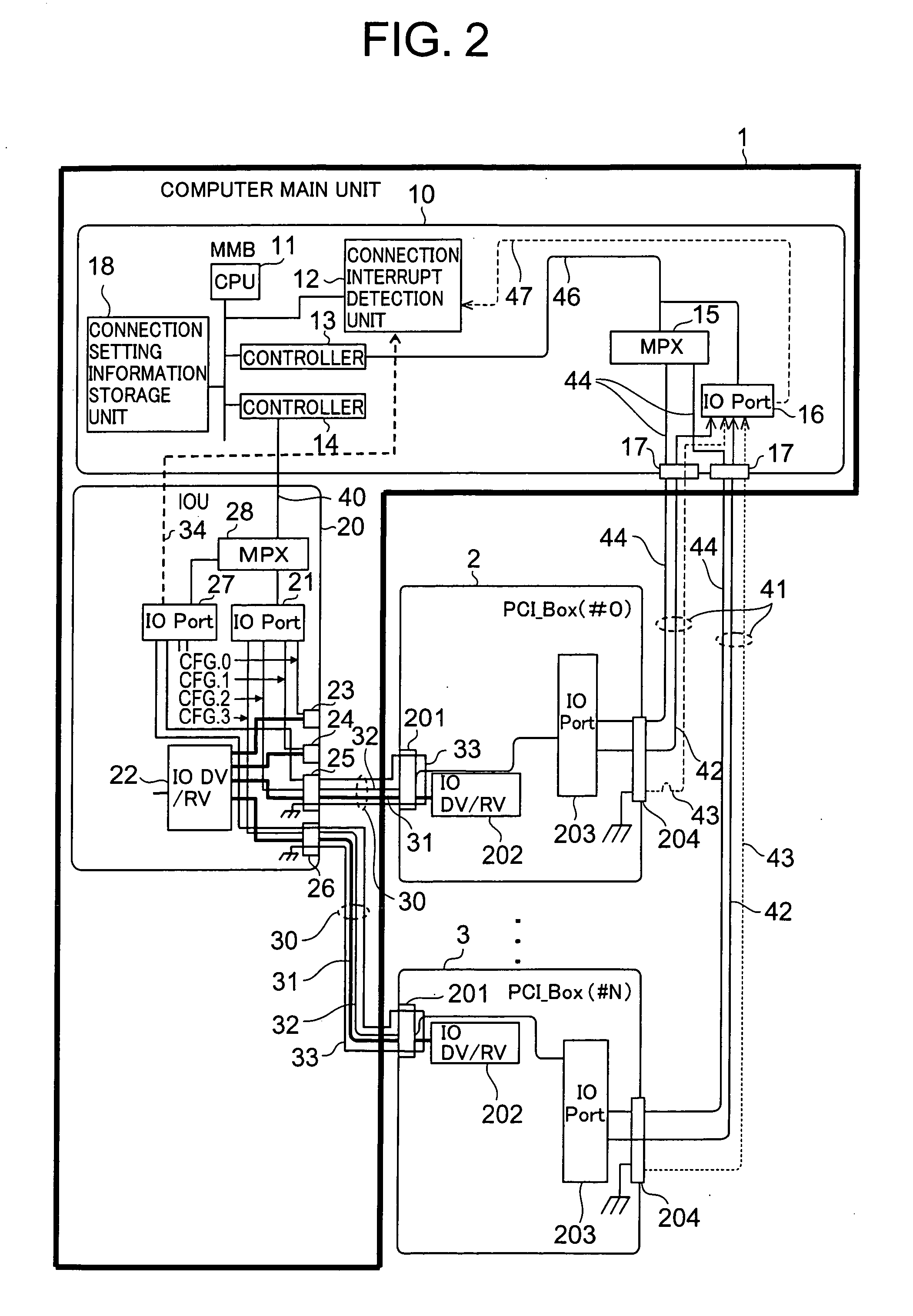
[0066] the present invention will be described in more detail with respect to a concrete example thereof. Referring to FIG. 2, the computer main unit 1 includes the MMB 10 and the IOU 20. The MMB 10 monitors and controls the connection between the IOU 20 and the PCI_Box (#0) 2 or between the IOU 20 and the PCI_Box (#N) 3 and the connections between the MMB 10 and the PCI_Boxes.

[0067] The MMB 10 includes a central processing unit (CPU) 11, a connection interrupt detection unit 12, controllers 13 and 14, a multiplex (MPX) 15, an IO port 16, connectors 17 and a connection setting information storage unit 18.

[0068] The controllers 13 and 14 and the MPX 15 are devices for bidirectional communication. The controllers 13 and 14 control each of the connections between the computer main unit 1 and the PCI_Boxes according to a direction from the CPU 11.

[0069] The MPX 15 multiplexes signals received from the PCI_Boxes, transmits the multiplexed signals to the controller 13, demultiplexes a s...

second embodiment

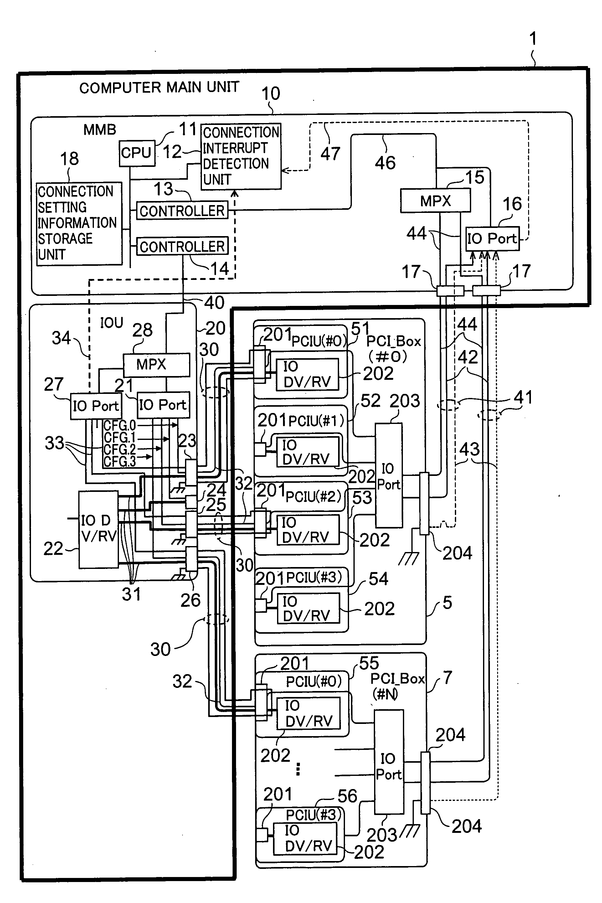
[0100] the present invention will next be described with reference to FIG. 3. In an IO device connection recognition system shown in FIG. 3, each of PCI_Boxes has a plurality of PCIUs as an IO expansion module adapted for partioning. Cables are connected on a PCIU-by-PCIU basis at the time of connection between the IOU 20 and the PCI_Box.

[0101] The second embodiment will first be outlined. The MMB 10 transmits a connection setting signal for setting a connection between the IOU 20 and one of the PCIUs in one of the PCI_Boxes to the PCI_Box via the IOU 20. In the PCI_Box, the connection setting signal is transmitted to a device capable of bidirectional communication in the PCI_Box (IO port 203 in the system shown in FIG. 3) via the PCIU connected to the IOU 20.

[0102] The device capable of bidirectional communication in each PCI_Box includes a register for a plurality of bits. When the device capable of bidirectional communication in the PCI_Box receives the connection setting signal...

third embodiment

[0160] In the third embodiment, when the IOU 20 and the PCIU are connected or disconnected by cable connection or cable disconnection, the bit logic on the interrupt pin assigned to the IO port 27 is changed according to the state of cable connection between the IOU 20 and the PCIU detected through the connection interrupt signal line 33. The IOU 20 sends the connection interrupt signal to the MMB 10 via the connection interrupt signal line 34.

[0161] The MMB 10 determines which PCIU has been connected to or disconnected from the IOU 20 by cable connection or cable disconnection on the basis of the bit logic on the interrupt pin assigned to the IO port 27 in the IOU 20.

[0162] In a case where one PCIU which is not identified from the connection setting information on the settings of connections between the IOU 20 and the PCIUs in the MMB 10 is newly connected to the IOU by cable connection, the MMB 10 establishes the connection between the PCIU and the IOU, as described below.

[0163]...


PUM


Abstract

A computer main unit and a PCI_Box (#0) are connected to each other in a loop connection manner by two paths. A first path is formed of an SMBus and a PCI_Box connection cable and a second path is formed of another PCI_Box connection cable. A monitoring and control unit (MMB) recognizes a connection path by reading out, through the second path, connection setting information written to the PCI_Box (#0) via the first path.

Description

CROSS-REFERENCE TO RELATED APPLICATIONS [0001] This application claims the conventional priority based on Japanese Application No. 2005-029999, filed on Feb. 7, 2005, the disclosures of which are incorporated herein by reference. BACKGROUND OF THE INVENTION [0002] 1. Field of the Invention [0003] The present invention relates generally to a technique of recognizing a connection between a computer main unit and an input / output (IO) expansion device and, more particularly, to a computer, an IO expansion device and a method for recognizing a connection of IO expansion device to realize connection or disconnection between a computer main unit and an IO expansion device on a partition-by-partition basis. [0004] 2. Description of the Related Art [0005] In recent years, the development of multiprocessor-type computer servers has been pursued. There is now a tendency to increase the scale of multiprocessor-type computer servers. There is also a demand for server systems capable of fine part...

Claims


Application Information

Patent Timeline
IPC IPC(8): G06F13/00
CPCG06F13/387G06F13/00G06F13/10
Inventor SHIMAZAKI, HARUO
Owner FUJITSU LTD
Why Eureka
Try Eureka