Structure of an over-current protection device and method for manufacturing the same

a protection device and structure technology, applied in the direction of semiconductor devices, semiconductor/solid-state device details, electrical apparatus, etc., can solve the problems of potential risk in use, difficult control of process, limited product yield, etc., and achieve easy control of process and yield, reduce manufacturing cost, and simple manufacturing

Inactive Publication Date: 2007-01-18
INPAQ TECH
View PDF0 Cites 2 Cited by
  • Summary
  • Abstract
  • Description
  • Claims
  • Application Information

AI Technical Summary

Benefits of technology

[0007] In view of the above-mentioned shortcomings of the conventional over-current protection device with a fusible fuse, the present invention is intended to provide a novel structure of an over-current protection device and manufacturing method thereof. The over-current protection device according to the present invention doesn't need to be filled with inert gas, nor does it need a tin sheet to be connected to an external electrode; thus, its manufacture is simple, and the process and the yield are easy to control, thereby reducing the manufacturing cost, which is an object of the present invention.

Problems solved by technology

The electrode needs to be connected to the ceramic fiber lead wound by a metal wire interiorly using the tin sheet by high-temperature melting, so that the process becomes difficult to control and its product yield is limited.
Thus, for this over-current protection device with a fusible fuse, when a high-energy inrushing current occurs during manufacturing, the ceramic pipe may explode due to instant expansion of the interior inert gas, causing a potential risk in use.

Method used


Image

  • Structure of an over-current protection device and method for manufacturing the same
  • Structure of an over-current protection device and method for manufacturing the same
  • Structure of an over-current protection device and method for manufacturing the same

Examples


embodiment 1

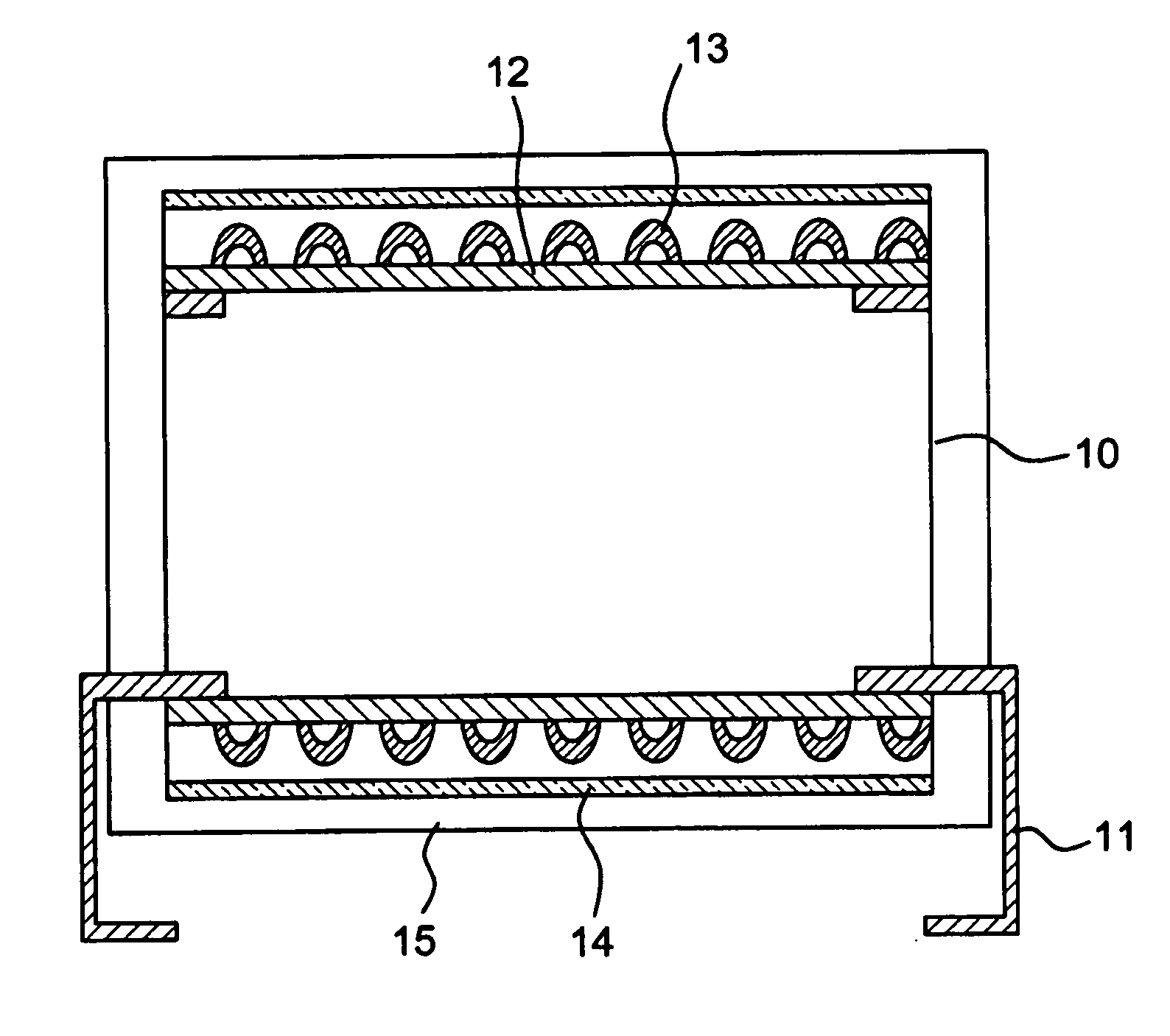
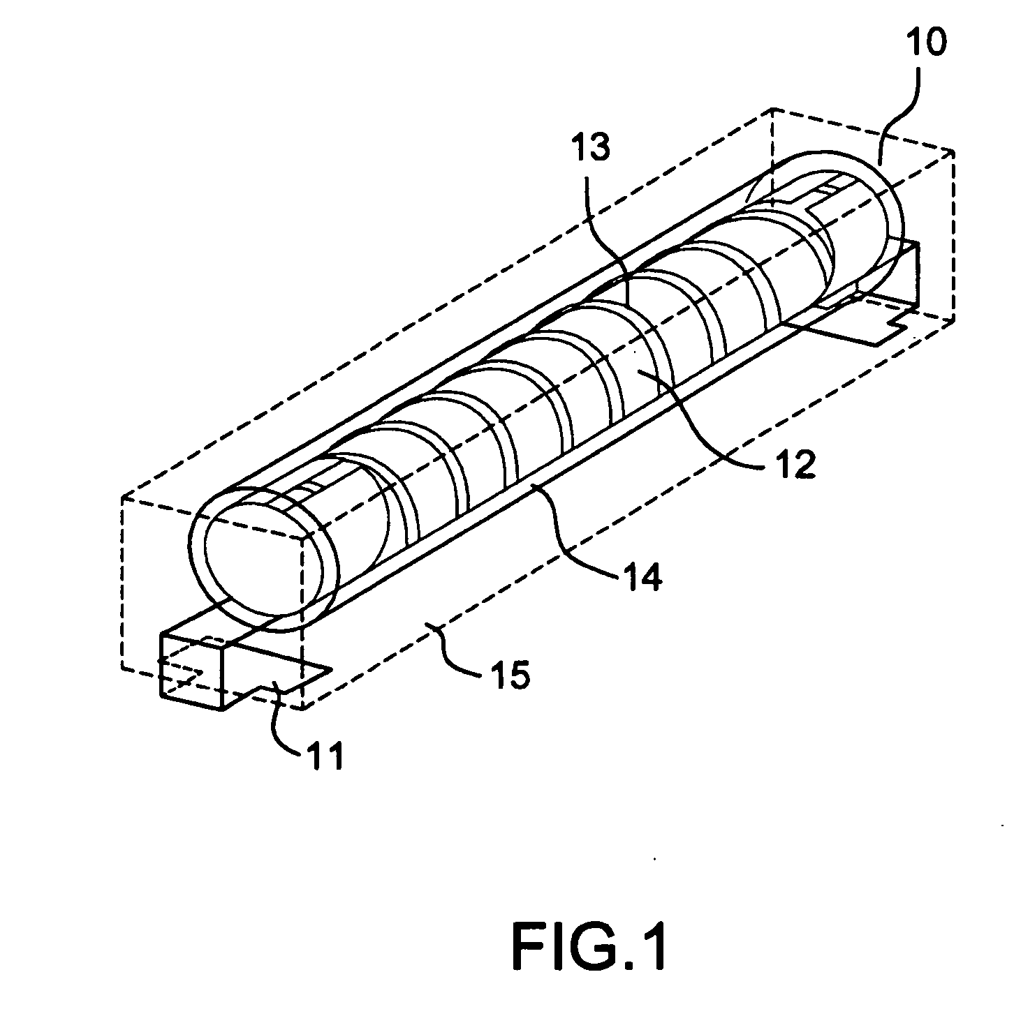
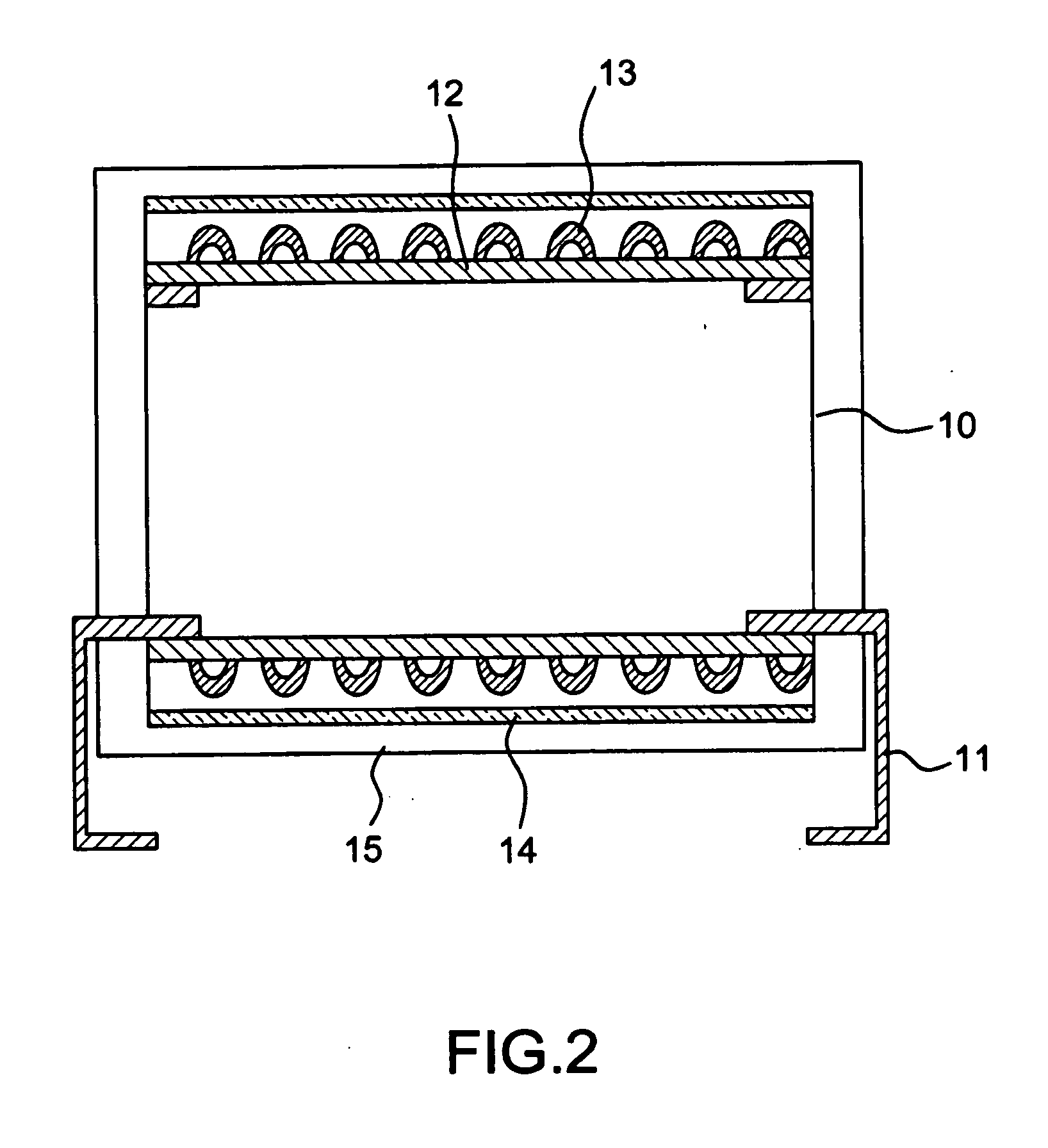
[0022] Steps of the batch type manufacturing manner are as follows: [0023] 1. Putting a finished ceramic fiber lead wound by a metal wire and a lead frame in a mould of predetermined dimensions, and connecting the lead frame to the metal wire; [0024] 2. After coating the exterior of the lead with a thermally-insulating material such as sodium silicate, forming an over-current protection device having a main body formed by a lead frame and a ceramic fiber lead wound by the metal wire by hot pressing. [0025] 3. While making the device, suction must be performed to form a vacuum state, so that water and small molecular materials dissolved due to heat during a heating process are removed. The suction can prevent the main body from forming voids if the water and small molecular materials remain in the cladding material, which will weaken the structural strength of the main body; on the other hand, the suction can get rid of water remaining in the structural layer of the cladding material...

embodiment 2

[0027] Steps of automatic continuous type manufacturing are as follows: [0028] 1. Putting a finished ceramic fiber lead wound by a metal wire and a lead frame in a reel-type carrier of predetermined dimensions, and connecting the lead frame to the wire; [0029] 2. After coating the exterior of the lead with a thermally-insulating material such as sodium silicate, making an over-current protection device having a main body formed by a lead frame and a ceramic fiber lead wound by a metal wire exteriorly, by using injection molding in conjunction with an automatic feeding mechanism. A mold should have exhaust holes for exhausting gases during the manufacturing of the finished products, so that water and small molecular materials dissolved due to heat during a heating process are removed, to prevent forming voids if the water and small molecular materials remain in the structural layer of the cladding material, which will weaken the structural strength of the main body; on the other hand...


PUM

PropertyMeasurementUnit
thermally-insulatingaaaaaaaaaa
melting indexaaaaaaaaaa
densityaaaaaaaaaa

Abstract

This invention is novel structure of an over-current protection device and manufacturing method thereof. The over-current protection device is formed with a main body with a lead frame and a ceramic fiber lead wound by a metal wire exteriorly, by coating the exterior of the whole lead with a thermally-insulating material, and then cladding the lead with a flame retardation material having an electrical insulation characteristic.

Description

BACKGROUND OF THE INVENTION [0001] 1. Field of the Invention [0002] The present invention relates to a method of manufacturing an over-current protection device, especially an over-current protection device configured by forming a main body structure with a lead frame and a ceramic fiber lead wound by a metal wire, coating the exterior of the whole lead part with a heat-insulating material, and then cladding it with a flame retardation material with an electrical insulation characteristic. [0003] 2. Description of the Prior Art [0004] In general, an over-current protection device used in telecommunication equipment is a telecommunication equipment protection fusible fuse (TEPFF), or called a telecommunication equipment protection module (TEPM). [0005] A conventional over-current protection device, which employs a fusible fuse to protect telecommunication equipment against damage caused by over current, is required to be of very high quality. Such an over-current protection device wi...

Claims


Application Information

Patent Timeline
Patent Type & Authority Applications(United States)
IPC IPC(8): H01L23/00
CPCH01H85/0078H01H85/0411H01H2085/0414H01H85/185H01H85/17
Inventor CHEN, CHING-CHIENCHANG, KUN-HUANGCHEN, YI-WEN
Owner INPAQ TECH
Why Eureka
Try Eureka