
Multi-level mapping of tape error recoveries
a technology of error recovery and tape head, applied in the field of multi-level mapping of tape error recovery, can solve problems such as data errors, media defects, debris between the tape head and the media,
- Summary
- Abstract
- Description
- Claims
- Application Information
AI Technical Summary
Benefits of technology
Problems solved by technology
Method used
Image

Examples
Embodiment Construction
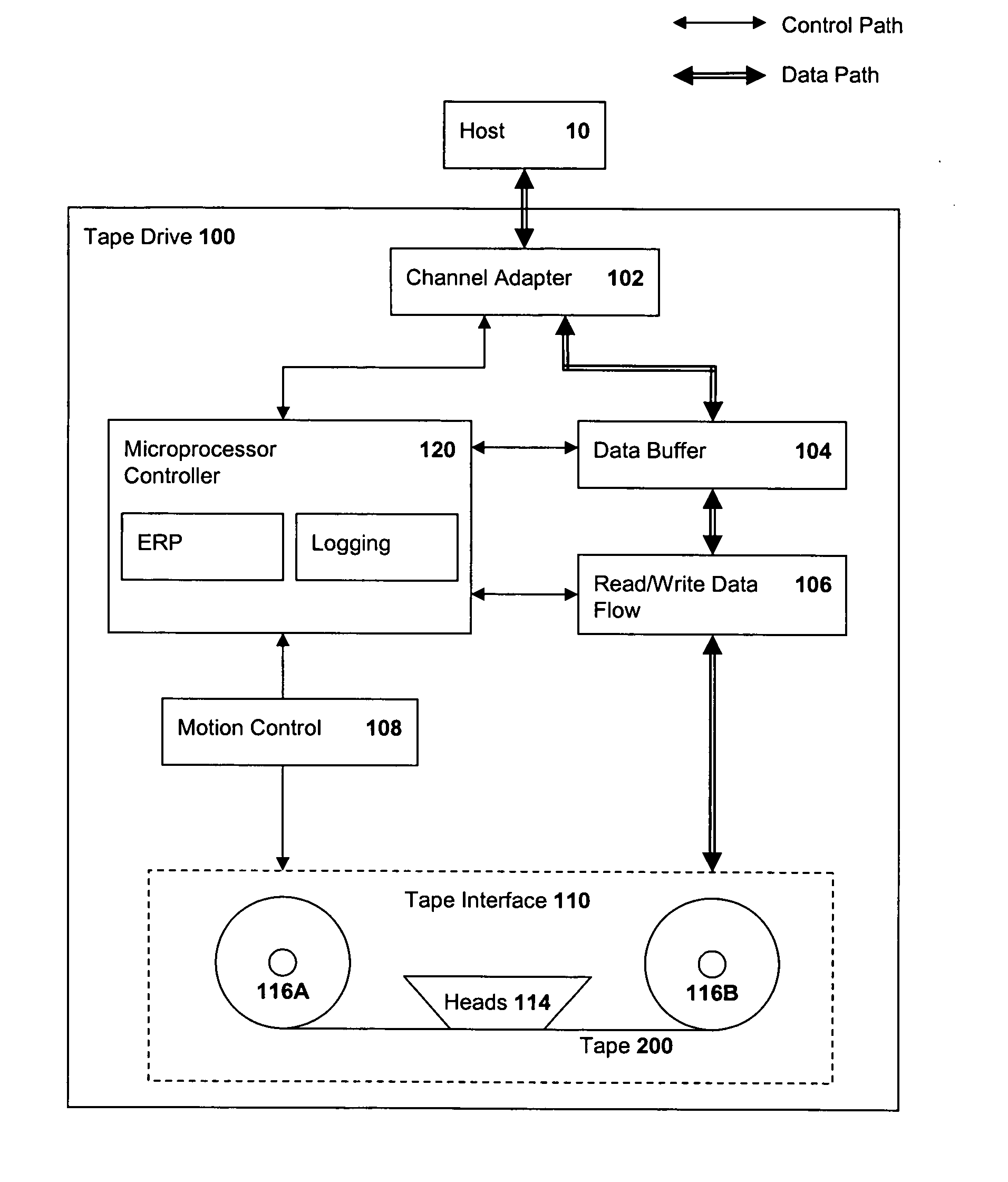
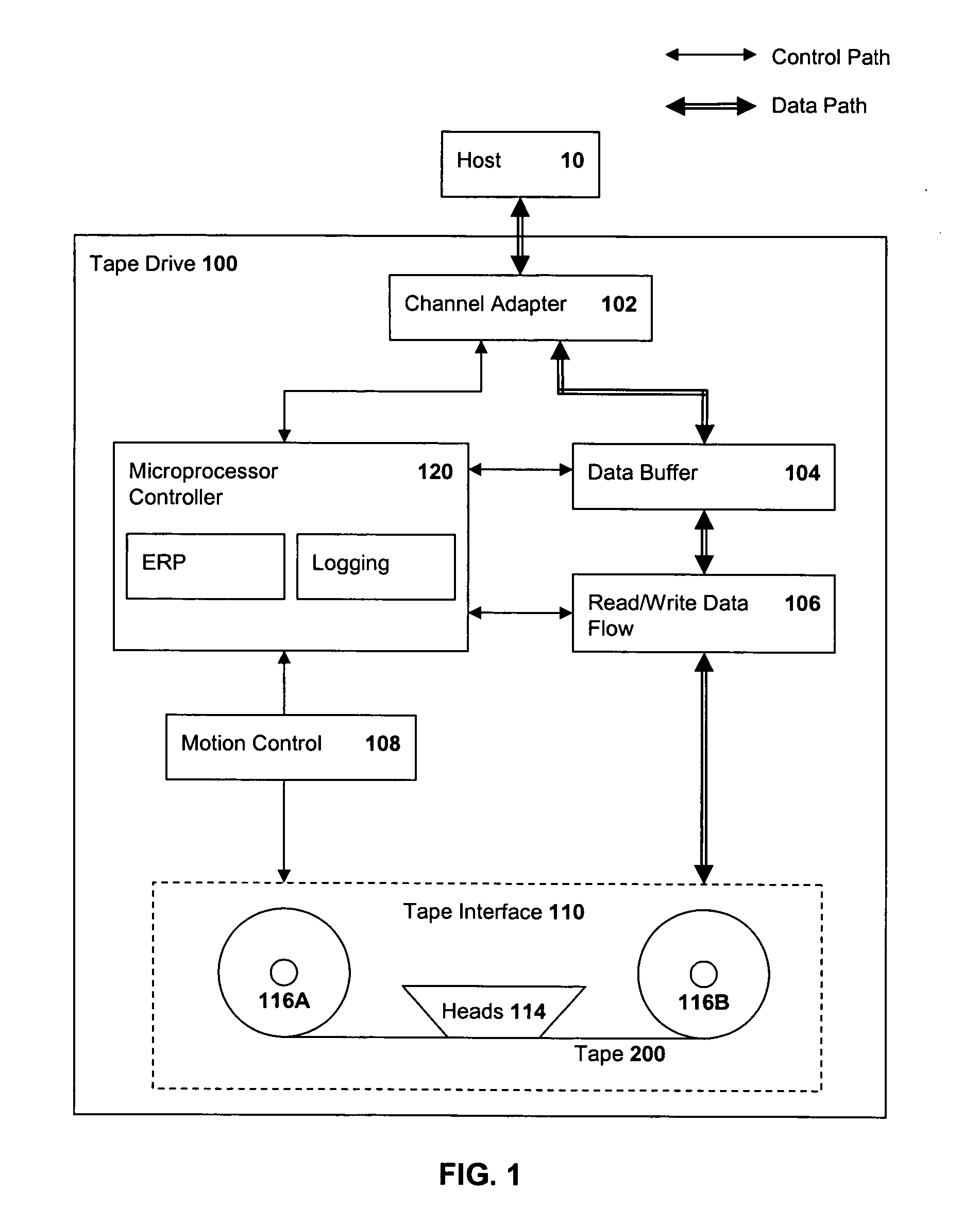
[0015]FIG. 1 is a block diagram of a magnetic tape drive 100 in which the present invention may be incorporated. The tape drive 100 is coupled to a host device 10 through a channel or host adapter 102 from which the drive 100 receives data to be stored to, and transmits data read from, magnetic tape 200. The tape drive 100 further includes a data path and a control path. The data path includes a data buffer 104, coupled to receive data from and send data to the adapter 102, and read / write data flow circuitry 106, coupled between the buffer 104 and a tape interface system 110. The control path includes a microprocessor controller 120, coupled to receive control signals from, and send control and response signals to, the host device 10 through the adapter 102, and a motion control circuitry 108, coupled between the microprocessor controller 120 and the tape interface system 110.
[0016] The microprocessor controller 120 provides overhead control functionality for the operations of all ...
PUM
| Property | Measurement | Unit |
|---|---|---|
| structure | aaaaa | aaaaa |
| densities | aaaaa | aaaaa |
| physical | aaaaa | aaaaa |
Abstract
Description
Claims
Application Information