Self-resetting, self-correcting latches

a latch and self-correcting technology, applied in the field of computer systems, can solve problems such as the loss of latch design, the system must be restarted, and the value can be upset,

Active Publication Date: 2007-02-01
IBM CORP
View PDF7 Cites 59 Cited by
  • Summary
  • Abstract
  • Description
  • Claims
  • Application Information

AI Technical Summary

Benefits of technology

[0013] It is therefore one object of the present invention...

Problems solved by technology

However, these values can be upset during microprocessor operation, e.g., from stray radiation or electrostatic discharge.
This upset is correctable by scanning a new value, but the system may only allow scanning at power-on, meaning that the system must be res...

Method used


Image

  • Self-resetting, self-correcting latches
  • Self-resetting, self-correcting latches
  • Self-resetting, self-correcting latches

Examples


Embodiment Construction

)

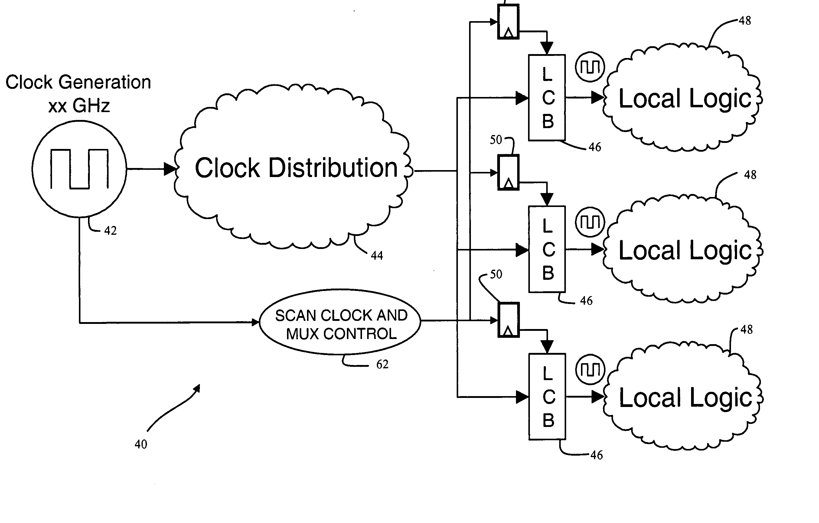
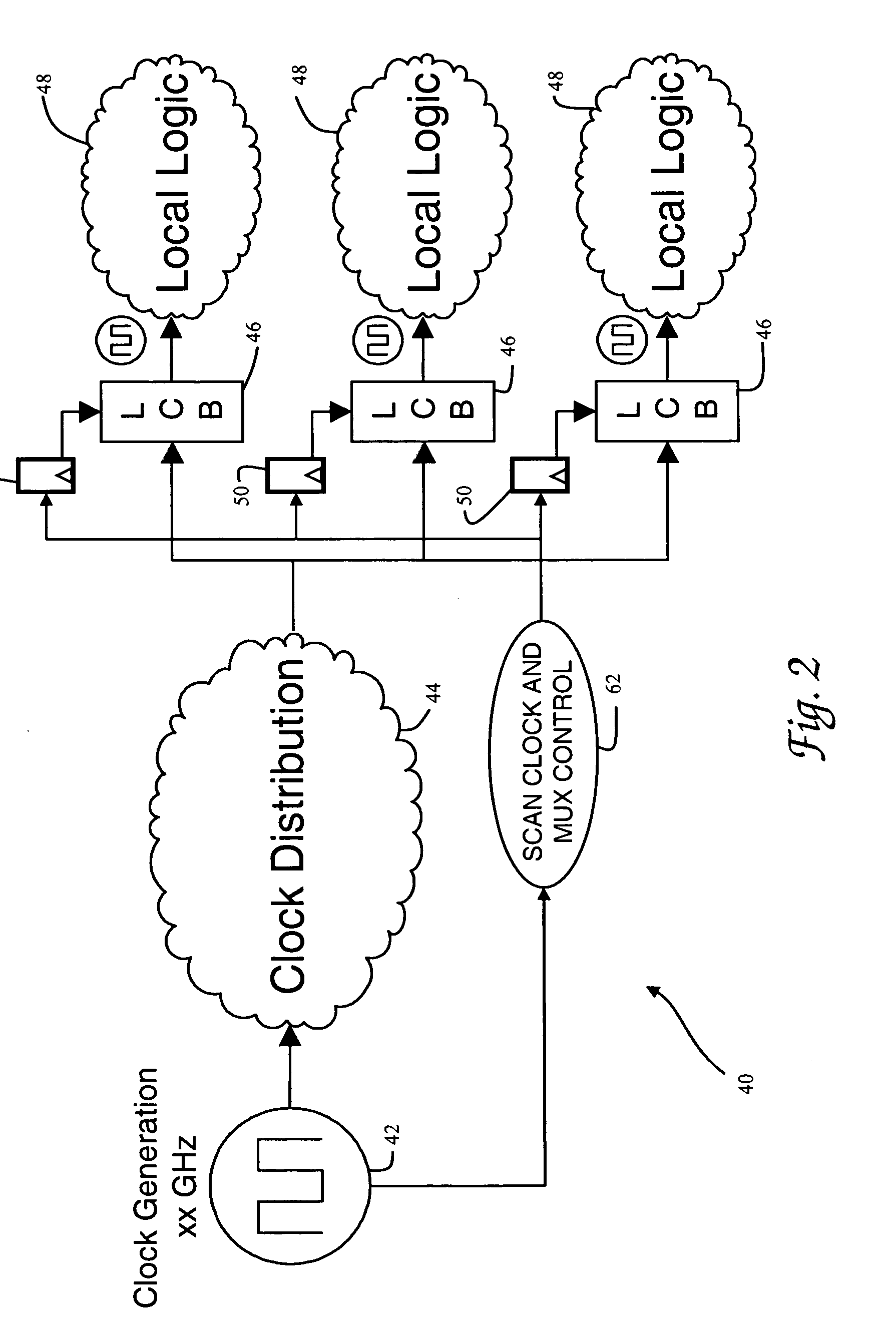
[0028] With reference now to the figures, and in particular with reference to FIG. 2, there is depicted one embodiment 40 of a clock control system which utilizes a novel latch circuit constructed in accordance with the present invention. Clock control system 40 is adapted for use within an integrated circuit such as a microprocessor. While clock control system 40 provides one example of how the invention may be implemented, those skilled in the art will appreciate that the invention is not so limited, and may be used in other latch control systems of a microprocessor besides clock control systems.

[0029] Clock control system 40 is generally comprised of a clock generation circuit 42, a clock distribution network 44, and a plurality of local clock buffers (LCBs) 46. Clock generation circuit 42 includes a phase-lock loop to create a master clock signal. The master clock signal is fed to the clock distribution network to render synchronized global clock signals at LCBs 46. Each LCB 4...


PUM


Abstract

A latch circuit having three latch stages generates a majority output value from the stages, senses when the latch stage outputs are not all equal, and feeds the majority output value back to inputs of the latch stages to reload the latch stages. The latch circuit uses a not-equal gate whose output is an error signal that can be monitored to determine when a single-event upset has occurred. A master stage is controlled by a first multiplexer which receives one system clock signal, while a slave stage is controlled by a second multiplexer which receives another system clock signal, and the latch stage outputs are connected to respective inputs of the not-equal gate, whose output is connected to second inputs of the multiplexers. The latch circuit is part of a latch control system, and reloading of the latch stages takes less than one cycle of the system clock (less than 500 picoseconds).

Description

CROSS-REFERENCE TO RELATED APPLICATION [0001] This application is a continuation-in-part of U.S. patent application Ser. No. 11 / 191,655 filed Jul. 28, 2005, which is hereby incorporated.[0002] This invention was made with Government support under PERCS II, DARPA contract NBCH3039004. THE GOVERNMENT HAS CERTAIN RIGHTS IN THIS INVENTION.BACKGROUND OF THE INVENTION [0003] 1. Field of the Invention [0004] The present invention generally relates to computer systems, specifically to a method of storing values in latches of a computer system, and more particularly latches which store state information for extended periods of time. [0005] 2. Description of the Related Art [0006] The basic structure of a conventional processing unit 10 for a computer system is shown in FIG. 1. In this example processing unit 10 is a dual-core processor having two processor cores 12a and 12b which carry out program instructions in order to operate the computer. Processing unit 10 also includes a memory subsys...

Claims


Application Information

Patent Timeline
IPC IPC(8): G06F11/08
CPCG06F11/1666G06F11/267G06F11/187G06F11/183
Inventor DRAKE, ALAN J.KLEINOSOWSKI, AJMARTIN, ANDREW K.
Owner IBM CORP
Why Eureka
Try Eureka