Fluorescent Lamp for Lighting Applications

a technology of fluorescent lamps and fluorescent lamps, which is applied in the field of fluorescent lamps, can solve the problems of adverse effects on the operation of the driver, adversely affecting the magnetic field of the transformer in the driver, damage to electronic components in the driver, etc., and achieves the effect of avoiding shortening the useful life of the driver

Inactive Publication Date: 2007-02-22
TBT ASSET MANAGEMENT INT
View PDF65 Cites 71 Cited by
  • Summary
  • Abstract
  • Description
  • Claims
  • Application Information

AI Technical Summary

Benefits of technology

[0010] When the driver is at an elevated temperature, the operation of the driver will be adversely effected. For example, the elevated temperature may adversely affect the magnetic field in a transformer in the driver and damage electronic components in the driver such as transistors and capacitors. By introducing a thermal insulator such as an air gap between the driver and the CCFL, heat transfer from the CCFL to the driver is inhibited, thereby preserving the integrity of the driver and its components, thereby avoiding shortening the useful life of the driver.
[0011] According to one embodiment of another aspect of the invention, a CCFL device comprises at least one layer of CCFL, having at least one CC...

Problems solved by technology

When the driver is at an elevated temperature, the operation of the driver will be adversely effected.
For example, the elevated temperature may...

Method used


Image

  • Fluorescent Lamp for Lighting Applications
  • Fluorescent Lamp for Lighting Applications
  • Fluorescent Lamp for Lighting Applications

Examples


Embodiment Construction

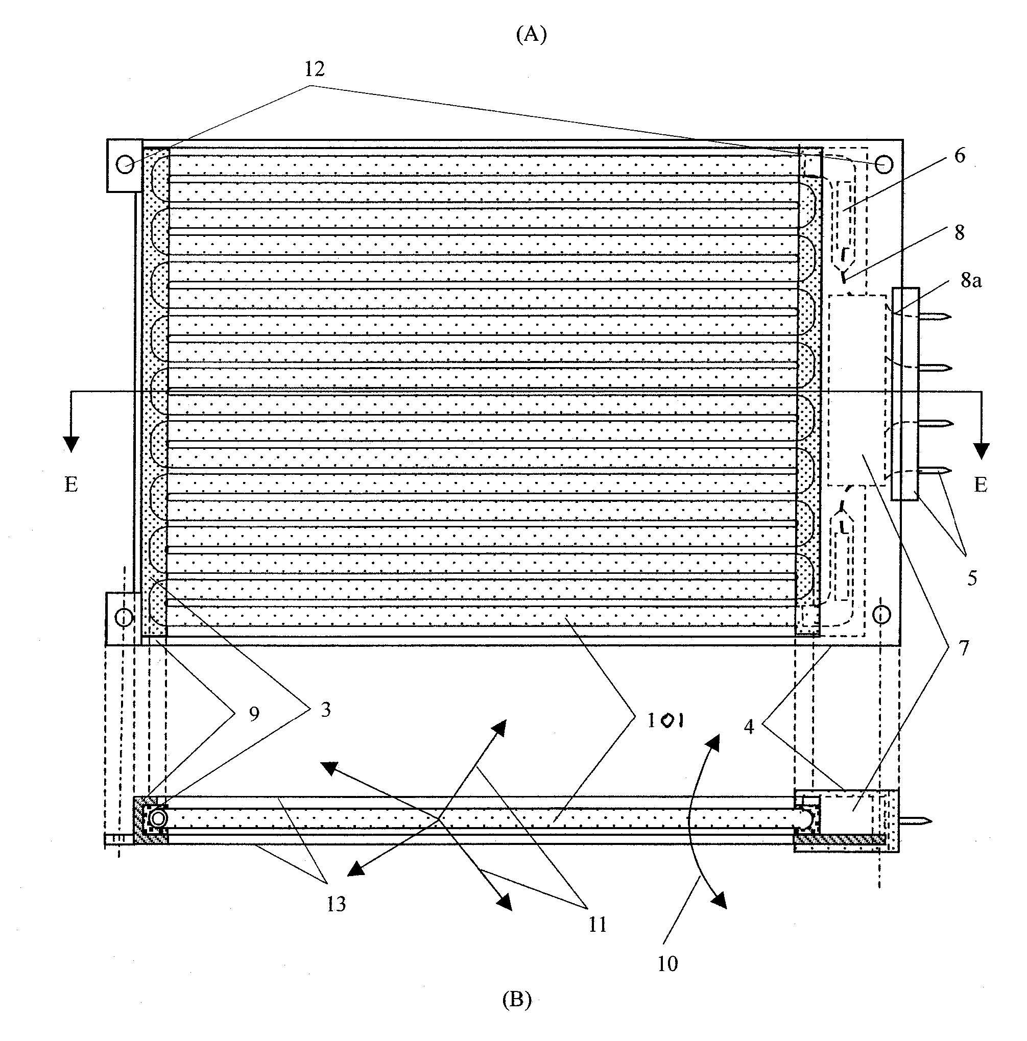
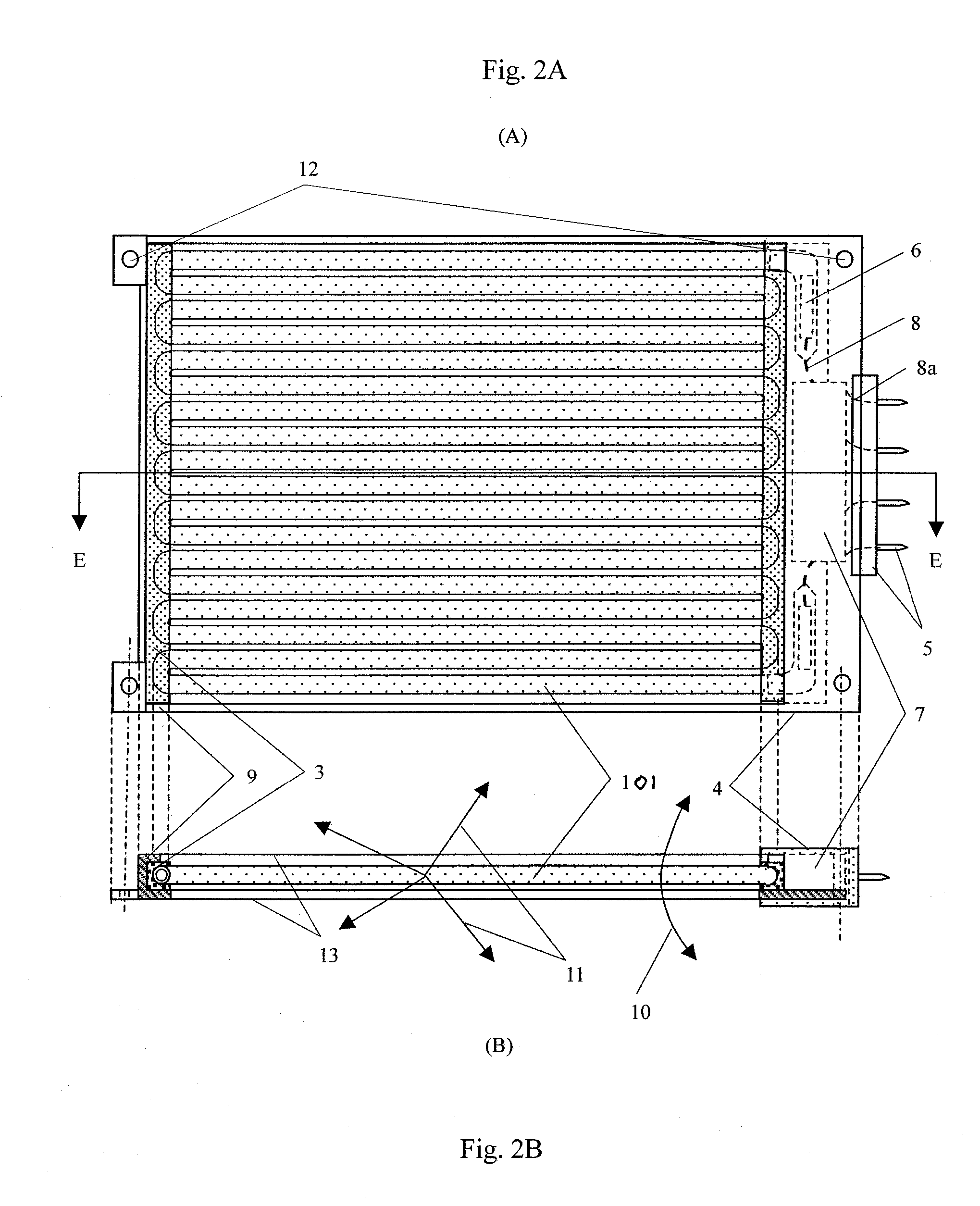
[0032] One embodiment of the invention provides a high efficacy, high light output, long lifetime, thin profile with good mechanical strength, dimmable and color adjustable flat light source that can be widely used in general lighting applications. It is based on the recognition that by providing a flat housing design, such that heat can be dissipated easily through air circulation of the CCFL in this housing, or thermal conduction through the CCFL supporting material of this housing, so that CCFL can be operated in this housing at a desirable temperature range of ˜70 C and heat generated by the CCFL cannot affect its controlling electronics, which is also housed in the vicinity of the CCFL.

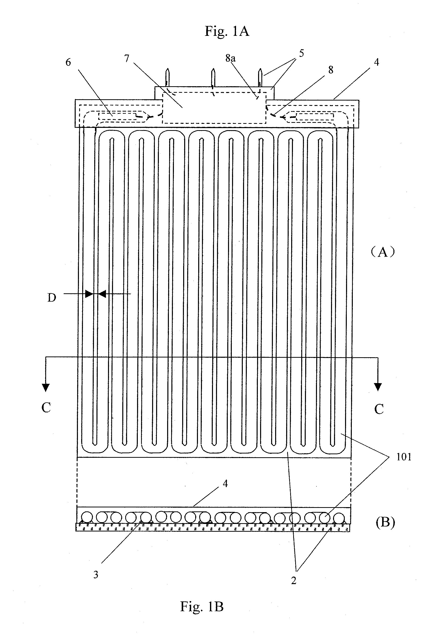
[0033]FIGS. 1A and 1B are respectively a schematic and cross sectional views of a CCFL device 100 to illustrate one embodiment of the invention. FIG. 1B is a cross sectional view of the fluorescent lamp of FIG. 1A along the line C-C in FIG. 1A. As shown in FIGS. 1A and 1B, a serpentine shaped CC...


PUM


Abstract

A lighting device comprises a serpentine shaped CCFL, a driver driving the CCFL, a connector that allows the device to connect to and receive power from conventional power sockets, and a fixture that connects them into a single device. Such device can be used for general lighting purposes and replaces incandescent and other fluorescent lamps in current use without having to change electrical sockets. The fixture mechanically connects the CCFL, the driver and the connector to form an unitary mechanical structure. Preferably an air gap is maintained between the CCFL and the driver.

Description

CLAIM OF FOREIGN PRIORITY [0001] This application claims the benefit of the following foreign applications: Chinese Applications No. 200520013482.0, filed Jul. 20, 2005; No. 200520013483.5, filed Jul. 20, 2005; No. 200520013484.X, filed Jul. 20, 2005; No. 200520116564.8, filed Nov. 21, 2005; and No. 200520116919.3, filed Dec. 1, 2005. BACKGROUND OF THE INVENTION [0002] 1. Field of the Invention [0003] The present invention relates generally to a fluorescent lamp and more particularly, to a fluorescent lamp for lighting. [0004] 2. Description of the Prior Art [0005] The existing high power tubular fluorescent lamps (FL), e.g., T12, T10, T8, T5 and T4 FL etc. are the hot cathode FL. It has been used for lighting beginning around 1940, and is widely used in the world now. It has the advantages of high efficiency, low cost and able to generate different color light. However, it has a short operating lifetime, and very short ON / OFF switching lifetime. It is also, difficult to control and...

Claims


Application Information

Patent Timeline
IPC IPC(8): F21L4/02
CPCH01J5/50H01J5/54H01J61/307H01J61/327H01J61/56H01J61/70H01J61/94
Inventor GE, SHICHAOLAM, VICTOR
Owner TBT ASSET MANAGEMENT INT
Why Eureka
Try Eureka