Display device and electronic apparatus

a technology of electronic equipment and display device, which is applied in the direction of discharge tube/lamp details, discharge tube luminescnet screens, electric discharge lamps, etc., can solve the problems of deteriorating image display characteristics, dark display image brightness, and extremely thin element itself, so as to reduce the brightness of display image, improve image display characteristics, and extract efficiently

Inactive Publication Date: 2007-04-19
SEMICON ENERGY LAB CO LTD
View PDF17 Cites 62 Cited by
  • Summary
  • Abstract
  • Description
  • Claims
  • Application Information

AI Technical Summary

Benefits of technology

[0008] It is an object of the present invention to propose a display device in which reflection of external light on a reflective polarizing plate is prevented and also extraction efficiency of light from a light-emitting layer is enhanced.
[0025] In the present invention, reflection of an outside image when external light is reflected on a reflective polarizing plate can be suppressed, and display characteristics of an image can be improved. In addition, light emitted in a light-emitting layer can be extracted efficiently, and decrease in brightness of a display image can be suppressed.

Problems solved by technology

Also, the element itself is extremely thin.
By using the metal having high reflexivity for the cathode, emission luminance from a light-emitting layer can be enhanced; however, on the other hand, there is a problem that an outside image is reflected when external light is reflected on the metal surface, which causes deterioration of image display characteristics, for example a viewer has difficulty in seeing a display image and brightness of the display image gets dark.

Method used


Image

  • Display device and electronic apparatus
  • Display device and electronic apparatus
  • Display device and electronic apparatus

Examples


embodiment mode 1

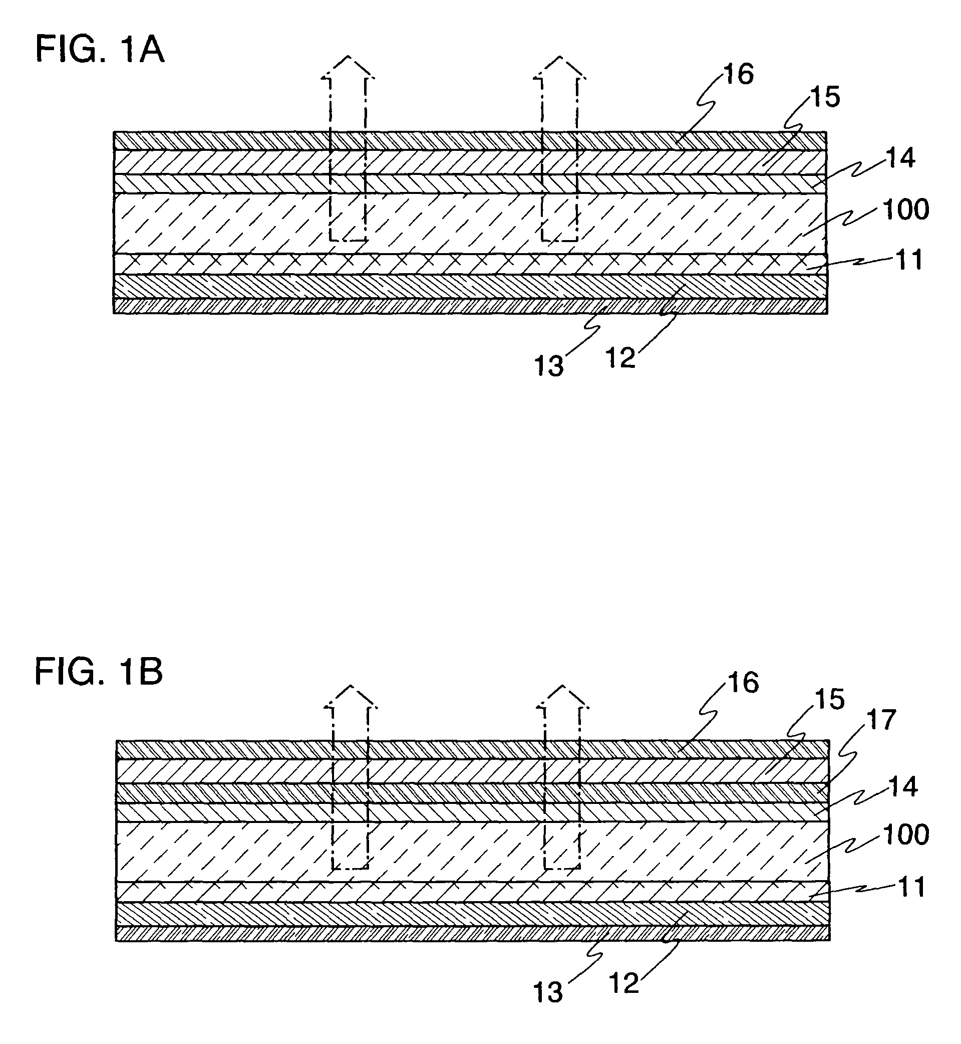
[0042] In this embodiment mode, a display device having a reflective polarizing plate, a quarter wave plate, and a polarizing plate will be explained. In FIGS. 1A and 1B, part of the display device of this embodiment mode is shown. It is to be noted that this structure is effective for displays such as PDP, SED, and FED as well as an organic EL display or an inorganic EL display.

[0043] In the display device of this embodiment mode, as shown in FIGS. 1A and 1B, a transparent electrode 11, a light-emitting layer 12, and a reflective electrode 13 are stacked over a substrate 100, and a reflective polarizing plate 14, a quarter wave plate 15, and a polarizing plate 16 are stacked over a surface of the substrate 100, which is opposite to the surface provided with the transparent electrode 11. In other words, the display device has a structure in which the reflective electrode 13, the light-emitting layer 12, the transparent electrode 11, the substrate 100, the reflective polarizing plat...

embodiment mode 2

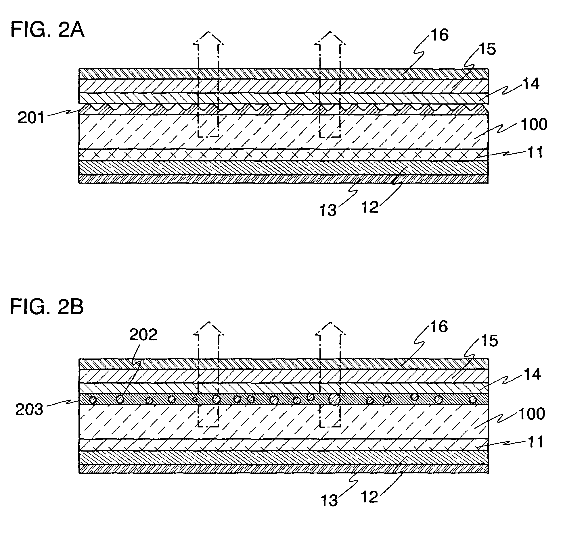
[0059] In this embodiment mode, a case where a prism layer is provided between a reflective polarizing plate 14 and a substrate 100 will be explained. It is to be noted that, in FIGS. 2A and 2B, the same portions as those in FIGS. 1A and 1B are denoted by the same reference numerals, and the explanation is omitted. In FIGS. 2A and 2B, part of a display device of this embodiment mode is shown.

[0060] In the display device of this embodiment mode, as shown in FIG. 2A, a transparent electrode 11, a light-emitting layer 12, and a reflective electrode 13 are stacked over a substrate 100, and a prism layer 201, a reflective polarizing plate 14, a quarter wave plate 15, and a polarizing plate 16 are sequentially stacked over a surface of the substrate 100, which is opposite to the surface provided with the transparent electrode 11. In other words, the display device has a structure in which the reflective electrode 13, the light-emitting layer 12, the transparent electrode 11, the substrat...

embodiment mode 3

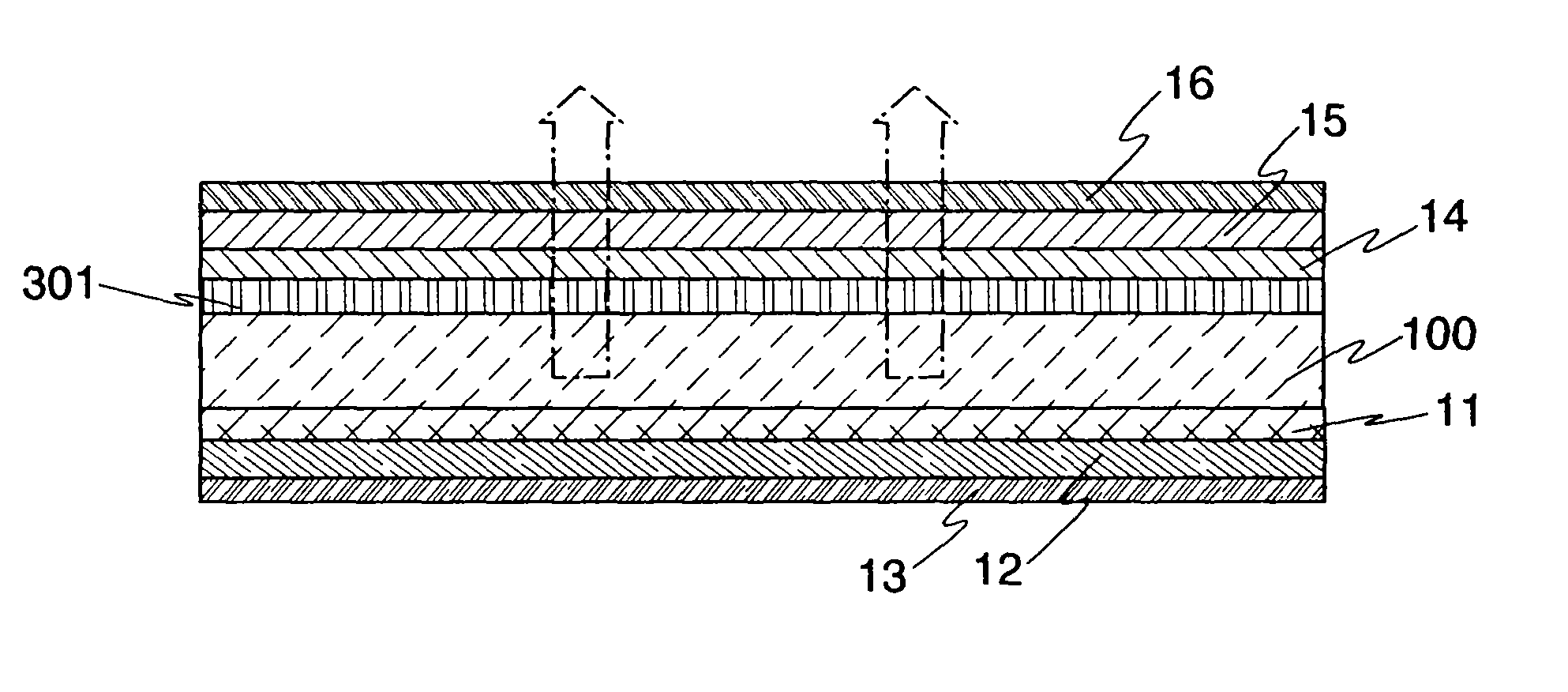
[0066] In this embodiment mode, a case where a quarter wave plate is provided between a reflective polarizing plate 14 and a substrate 100 will be explained. It is to be noted that, in FIG. 3, the same portions as those in FIGS. 1A and 1B are denoted by the same reference numerals, and the explanation is omitted. In FIG. 3, part of a display device of this embodiment mode is shown.

[0067] In the display device of this embodiment mode, as shown in FIG. 3, a transparent electrode 11, a light-emitting layer 12, and a reflective electrode 13 are stacked over the substrate 100, and a quarter wave plate 301 (referred to as a first quarter wave plate), the reflective polarizing plate 14, a quarter wave plate 15 (referred to as a second quarter wave plate), and a polarizing plate 16 are stacked over a surface of the substrate 100, which is opposite to the surface provided with the transparent electrode 11. In other words, the display device has a structure in which the reflective electrode ...


PUM


Abstract

It is an object to propose a display device in which reflection of external light on a reflective polarizing plate is prevented and also extraction efficiency of light from a light-emitting layer is improved. If the display device has a light-emitting layer provided over a reflective electrode, a transparent electrode provided over the light-emitting layer, a transparent substrate provided over the transparent electrode, a reflective polarizing plate provided over the transparent substrate, a quarter wave plate provided over the reflective polarizing plate, and a polarizing plate provided over the quarter wave plate, reflection of an outside image can be suppressed, and light emitted in the light-emitting layer can be extracted efficiently.

Description

BACKGROUND OF THE INVENTION [0001] 1. Field of the Invention [0002] The present invention relates to a display device in which an element having a structure including an anode, a cathode, and a thin film which emits light by electroluminescence (hereinafter, referred to as “EL”) interposed between the anode and the cathode is provided over a substrate. [0003] 2. Description of the Related Art [0004] An EL element is an element which obtains light emission by forming a thin film containing an organic compound or an inorganic compound, or a crystal between a cathode and an anode and feeding current between the cathode and the anode. In recent years, especially an EL element in which a thin film containing an organic compound as its main constituent (hereinafter, referred to as a light-emitting layer) is placed between a cathode and an anode, i.e., an organic EL element, has been actively developed. [0005] An organic EL element is expected to be applied in various fields, and is consid...

Claims


Application Information

Patent Timeline
Patent Type & Authority Applications(United States)
IPC IPC(8): H01J1/62H01J63/04
CPCH01L27/3244H01L51/5281H01L51/5268H10K59/12H10K50/854H10K50/86
Inventor HIRAKATA, YOSHIHARUYAMAZAKI, SHUNPEI
Owner SEMICON ENERGY LAB CO LTD
Why Eureka
Try Eureka