Touch key assembly for a mobile terminal

a mobile terminal and assembly technology, applied in the field of mobile terminals, can solve the problems of undesirable increase in the power requirements affecting the reflection of light, and the thickness of the gap necessarily increasing the thickness of the mobile terminal, so as to achieve the effect of enhancing the reflection of ligh

a mobile terminal and assembly technology, applied in the field of mobile terminals, can solve the problems of undesirable increase in the power requirements affecting the reflection of light, and the thickness of the gap necessarily increasing the thickness of the mobile terminal, so as to achieve the effect of enhancing the reflection of ligh

US20070103453A1Active Publication Date: 2007-05-10LG ELECTRONICS INC

Image

  • Touch key assembly for a mobile terminal
  • Touch key assembly for a mobile terminal
  • Touch key assembly for a mobile terminal

Examples


Embodiment Construction

[0036] Reference will now be made in detail to the preferred embodiments of the present invention, examples of which are illustrated in the accompanying drawings. Wherever possible, the same reference numbers will be used throughout the drawings to refer to the same or similar parts.

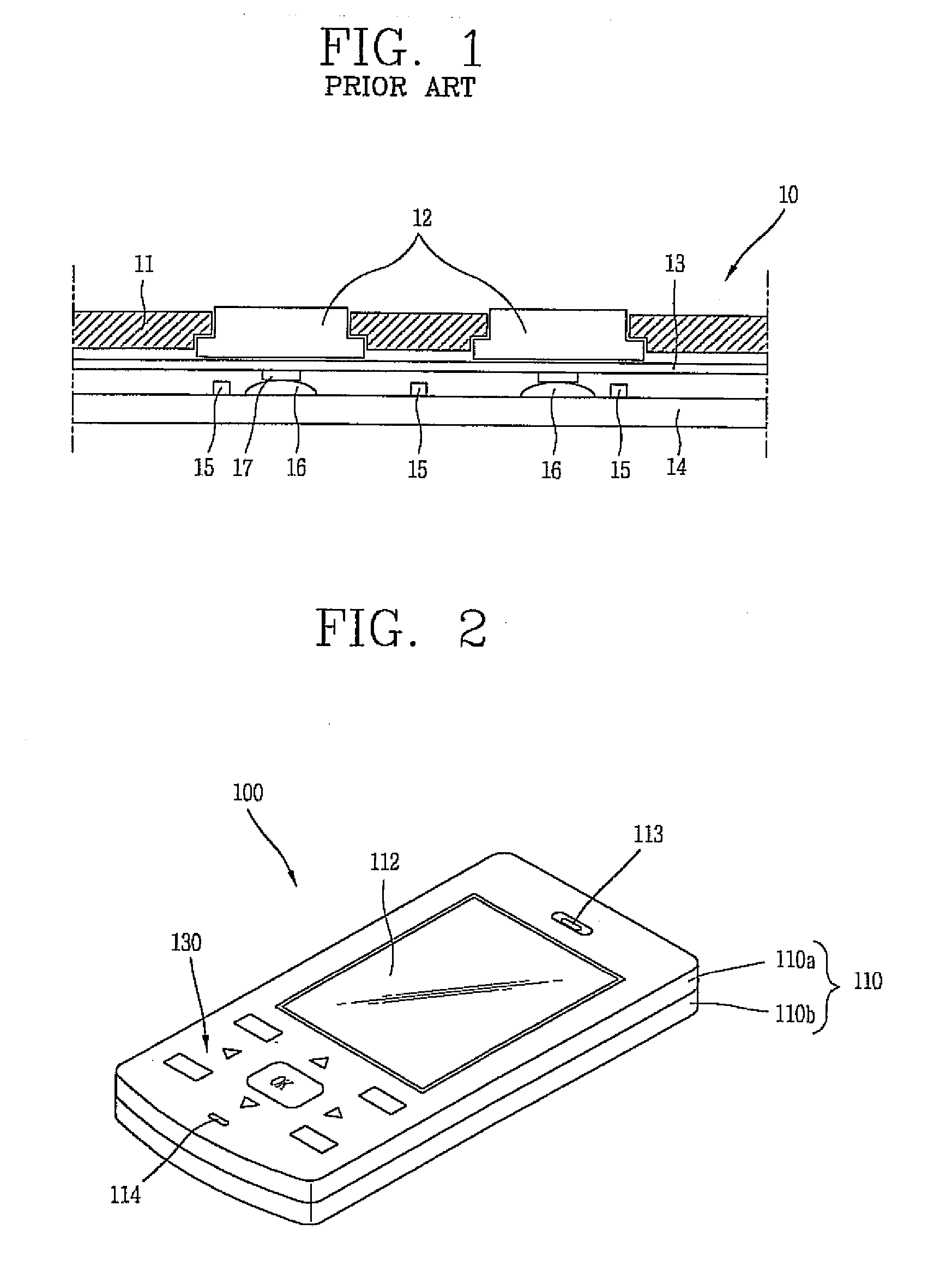
[0037]FIG. 2 is a perspective view of a mobile terminal according to an embodiment of the present invention. As shown, mobile terminal 100 includes body 110, which has display 112, speaker 113, and touch key assembly 130 formed on an upper side of the body. Body 110 is further defined by first body 111a and second body 110b. The touch key assembly is located at one end of the first body, below the display. The touch key assembly may be used to receive input from a user, and thus may include one or more touch keys (described in more detail in later figures). In an embodiment, various touch keys of touch key assembly 130 may be configured to cooperate with items presented on display 112.

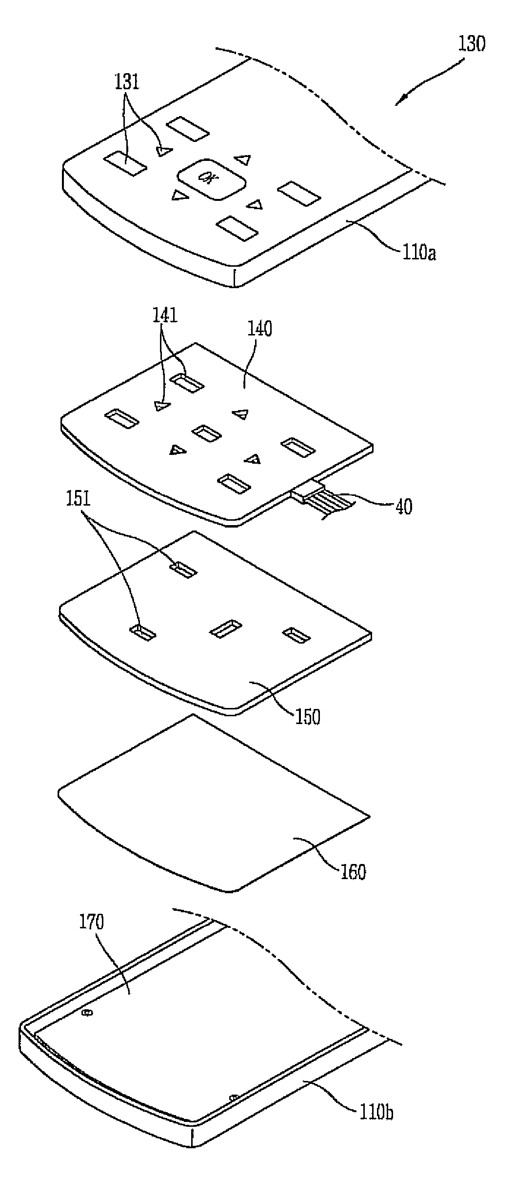
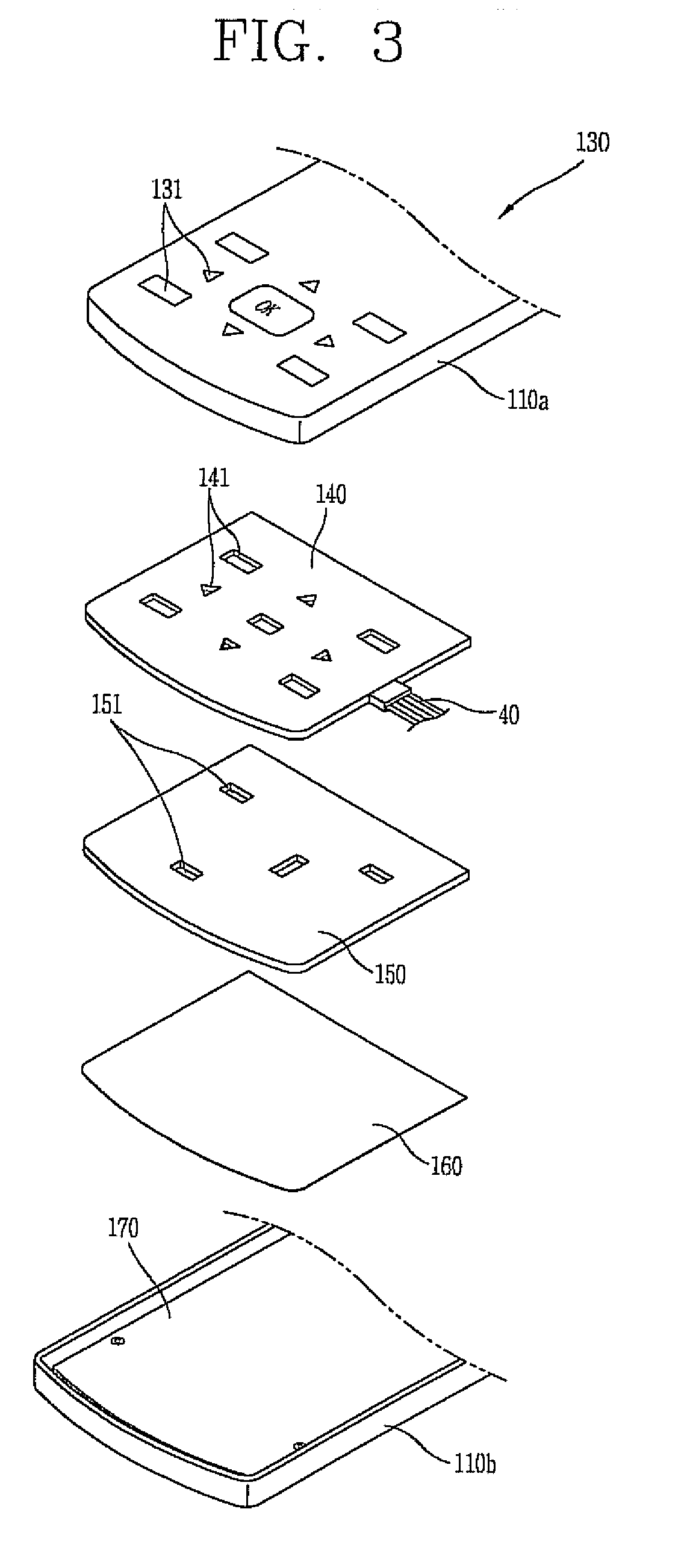
[0038]FIG. 3 is p...


PUM

PropertyMeasurementUnit
thinner dimensionsaaaaaaaaaa
thicknessaaaaaaaaaa
poweraaaaaaaaaa

Abstract

A touch key assembly includes a cover having at least one touch key which is identified by an optically transmissive region of the cover. The cover is also shaped to define a push key opening. The assembly also includes a touch pad structured to operatively couple to the cover such that the touch pad is positioned relative to the touch key. A push key is positioned within the push key opening of the cover. The touch key assembly may be implemented in a portable electronic device, such as a mobile terminal or a personal digital assistant (PDA).

Description

CROSS-REFERENCE TO RELATED APPLICATIONS [0001] This application is a continuation of U.S. application Ser. No. 11 / 468,532, filed Aug. 30, 2006, currently pending, which pursuant to 35 U.S.C. ยง 119(a), claims the benefit of earlier filing dates and right of priority to Korean Application Nos. 80371 / 2005 filed on Aug. 30, 2005, and 136199 / 2005 filed on Dec. 30, 2005, the contents of which are hereby incorporated by reference herein in their entirety.BACKGROUND OF THE INVENTION [0002] 1. Field of the Invention [0003] The present invention relates to a mobile terminal, and more particularly to a touch key assembly structured to include a push key. [0004] 2. Discussion of the Related Art [0005] A mobile terminal is one type of portable electronic device capable of wireless communication in a mobile environment. Common mobile terminals include mobile phones, personal digital assistants (PDSs), and the like. Consumers have demanded mobile terminals with increasingly thinner dimensions. In ...

Claims


Application Information

Patent Timeline
10 May 2007
Publication
US20070103453A1
IPC
G09G5/00; G06F3/02; G06F3/0354; G06F3/041; H04M1/22
CPC
G06F3/03547; H01H13/83; H01H2201/036; H01H2207/004; H01H2219/014; H01H2219/038; H01H2219/06; H01H2219/062
Inventors
CHOO, ZHI-MIN; LEE, HYUNG-WOON